| < Previous page | Next page > |
Banks Menu
These routines can be used for creating an individual "contour bank" or network/networks of "contour banks".
What is a contour drain / bank.
A contour bank is cut across a slope. It's aim is to reduce the length that water can run down the slope. This reduces it's velocity and the amount of erosion that can occur. In agricultural situations this bank/drain is often grassed to hold the bank together and reduce erosion on the bank itself.
The screen shot below shows an example of what can be achieved:
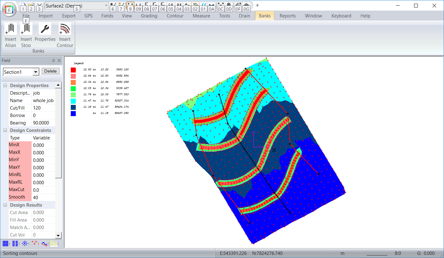
If you look at the screen-shot above we can see that the design and construction consists of 4 main parts. The black alignment is the centre-line of the completed network. It consists of a number of nodes and is clicked in by the user. Once designed the user can click on a node to select the node. You can then delete or drag the node. You can also click in an additional node. You can also select the alignment and delete the complete alignment.
You can also see the red alignments on the sides. These are optional. If they are not there the bank designed will extend to the edge. If they are there the bank will be chopped off where it intersects one of these stopping alignments. Again you can edit these stopping alignments by clicking a node and deleting or dragging. You can also select and delete the whole stopping alignment.
The last component is the actual contour bank. In the screen shot above we actually have designed 8 banks. Four are left of the alignment and four to the right. The right banks are designed with steeper slope than the ones to the left.. For a continuous bank you can design the alignment along the edge and only design the banks on one side. In the example above the banks would tend to store water along the alignment in heavier rain. If you wanted water to drain off the edges then the banks would be designed with a negative slope.
Insert Alignment
Here we are creating an alignment. The contour banks that are subsequently created lie approximately perpendicular to this alignment.
We draw in the bank-alignment drain as a series of line segments. Firstly left click on the screen. Now move the mouse and left click again at the second node. Keep going until you are happy with what you have. Click the "Enter" key to finish the process or "escape" key to abandon the complete entry. The process is the same as entering section links or a drain profile. Once complete the plan view of the alignment is shown.
Insert Stop Alignment
When the contour banks are created by default they continue till the edge or will stop if there is no possible solution. You can control the finish of the contour-bank with a stop line. Once the contour-bank hits it; its is automatically truncated at this point. The alignment is inserted the same as the normal alignment. It is displayed in a red color to signify it is a stop line.
Calculate
This routine controls the calculation of the contour banks.
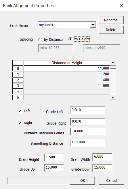
To calculate the banks fill in this dialog and hit the OK key. The function of the parameters are:
Bank Name: This is the name of the alignment that is being used. If you have more than one alignment defined; you can select the correct alignment from the drop down combo box.
Rename and Delete: Either Rename or Delete the alignment currently used depending on button pressed.
Spacing: This tells us how we are defining the start position of the contour bank along the alignment. There are two options
If we select By Distance then we start a contour bank at all the distance's in the table; specified from the start of the alignment. If we do it by height then we start at the point along the alignment at the appropriate height.
Distance or Height Table: Here we fill in the appropriate values that are to be used. You fill in the table in a similar way to an excel spreadsheet. Click into the appropriate cell and start typing. You can delete an entry by left clicking into the left most column (number column) and hit the delete key.
Left tick box: Click this if you want a contour bank on the left of the alignment and fill in a grade to be used. Positive grade gives increasing height while negative is decreasing.
Right tick box: Similar to left side.
Distance between points: This value in meters or feet is the distance between points calculated along the new contour bank. We suggest you experiment to decide on the distance best suited to your application and the changes of grade in the job.
Smoothing Distance: On natural surface models we often have hills and hollows and it may be not physically possible to create a design. For example if you have a hole in the system then the mathematical solution will curl around and stop in the centre. If you have a flat area but you need to drop 1% then again it is a mathematical impossibility. If you specify a smoothing distance then the current surface has a smoothing algorithm applied to it and we work on this model. This normally gives us a better result as well as a more pleasing contour bank to work with.
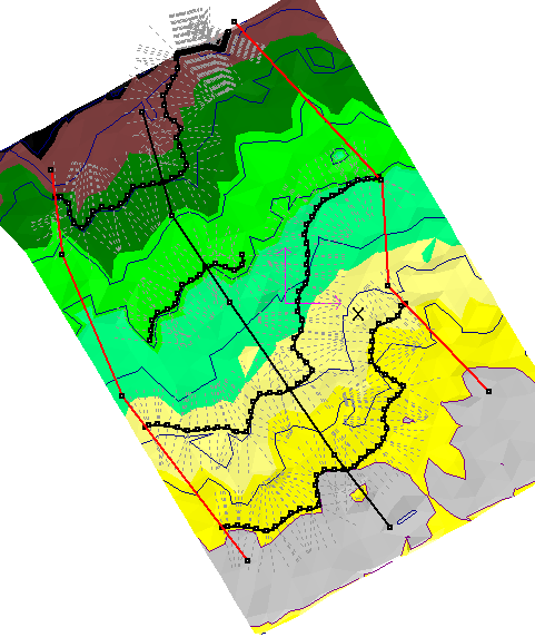
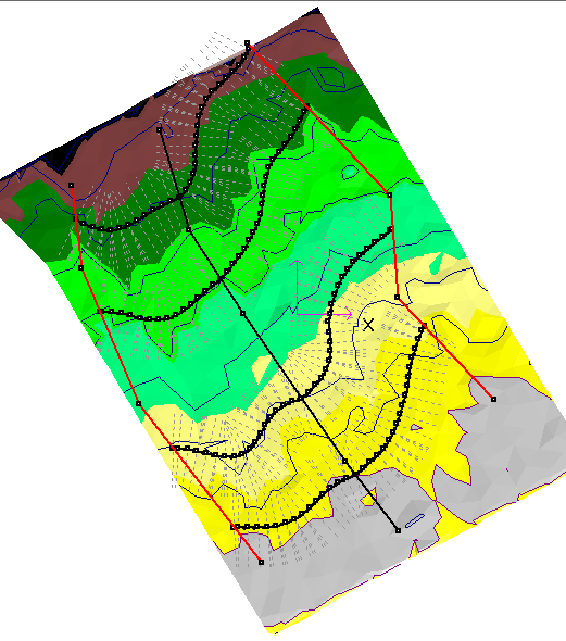
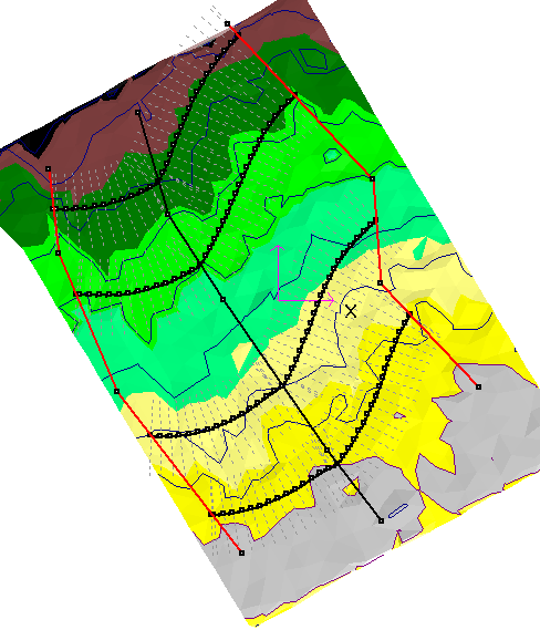
Here are some examples of contour banks created with different smoothing differences:
If you are designing along a design surface then the existing surface is used as is with no smoothing.
A hint:
Look at the example above with zero smoothing. Look at the 3rd bank up to the left and look where the bank stops prematurely. You can see that the 1% contour bank is slowly rising away from the contour line shown. Where the contour bank finish's you can see there is a sharp bend in the existing contour. The contour bank algorithm only looks for a valid solution withing 90 degrees of the last segment. In this case there is a correct mathematical solution but in practise you dont want to construct contour banks with sharp curves so we stop.
The smoothed example's finish successfully as we don't get the sharp corners of the unsmoothed case.
Insert Contour
You use this routine to design an individual contour bank. You can design as many as required and can start anywhere. This gives you the ultimate control. Clicking on the "Insert Contour" brings up the following dialog:
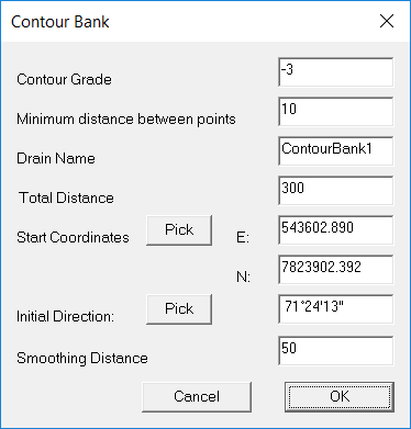
You need to enter the follwing values.
Contour Grade - This is the grade as a percentage. We have a grade of -3% entered here. Negative means that the height is decreasing as we go along the bank. Simply enter 3 for an increasing height of 3%.
Minimum distance between points: This is a value in either meters or feet. In the final design points making up the contour bank are placed this distance apart.
Drain Name: Make sure we have a unique name for each contour bank.
Total distance: You can force the bank to stop at a certain distance rather than extend all the way to the edge of the job.
Start Coordinates: Please enter the easting and northing values if you know them. Alternatively click on the "Pick" button and the dialog closes down. You then move the cursor to the appropriate point in the job and left click. The dialog is reshown with the appropriate start coordinates.
Initial Direction: This tells the dialog which way the contour bank is to run. Normally on a down slope there are two ways that the bank can run across the grade. By entering this value we get the bank running in the correct direction. If you click on the "Pick" button the dialog disappears and you can click in a direction. First click on the screen and then move the mouse. A direction is shown. Left click again to finish. The initial direction is shown. As already mentioned this is only an initial guess. The routine finds the best direction to follow based on this initial guess. It looks left and right at an angle up to 90 degrees.
Cancel: Closes down the dialog and nothing is done.
OK: This button runs the routine and creates the drainage bank. The bank is designed with the profile running along the surface and default section for the bank. The bank design needs to be changed using the drain routines.
|