| < Previous page | Next page > |
Design within Ezigrade
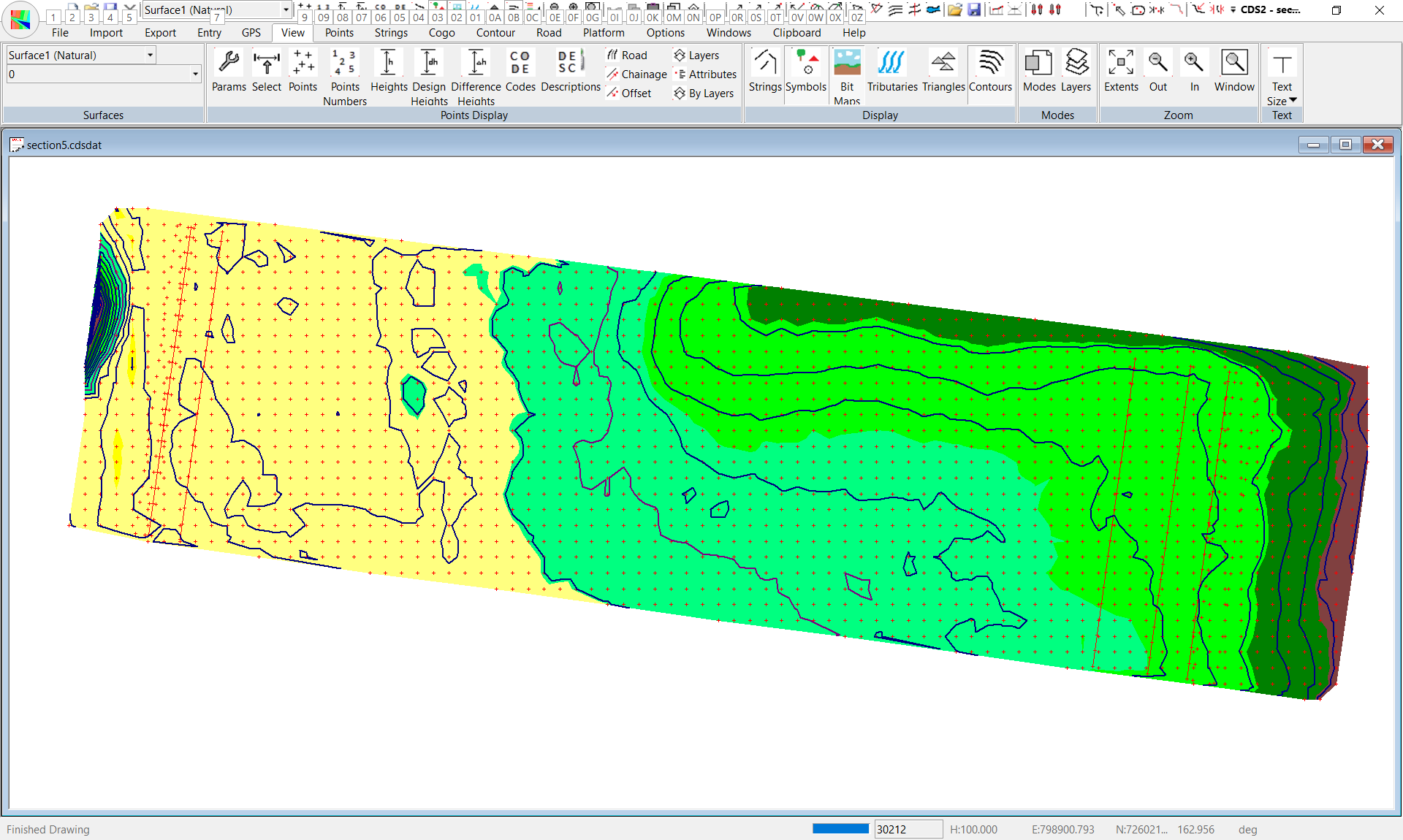
In this method we are going to create two sections. One is the field and the other is the sill. These need to move in unison. Hence we will hinge them together. Looking again at our plan view within Ezigrade. We have 5 strings displayed. For the sections we are interested in the left edge of section, the right edge of section and the start of the sill.
The existing string is the right edge of the table drain. Within Ezigrade we are going to use this as a guide when we click in the table drain. However we really want the center of the table drain. Similarly we want the center of the head ditch, not the left edge. So I suggest at this stage that you go back into CDS and calculate these two extra string lines.
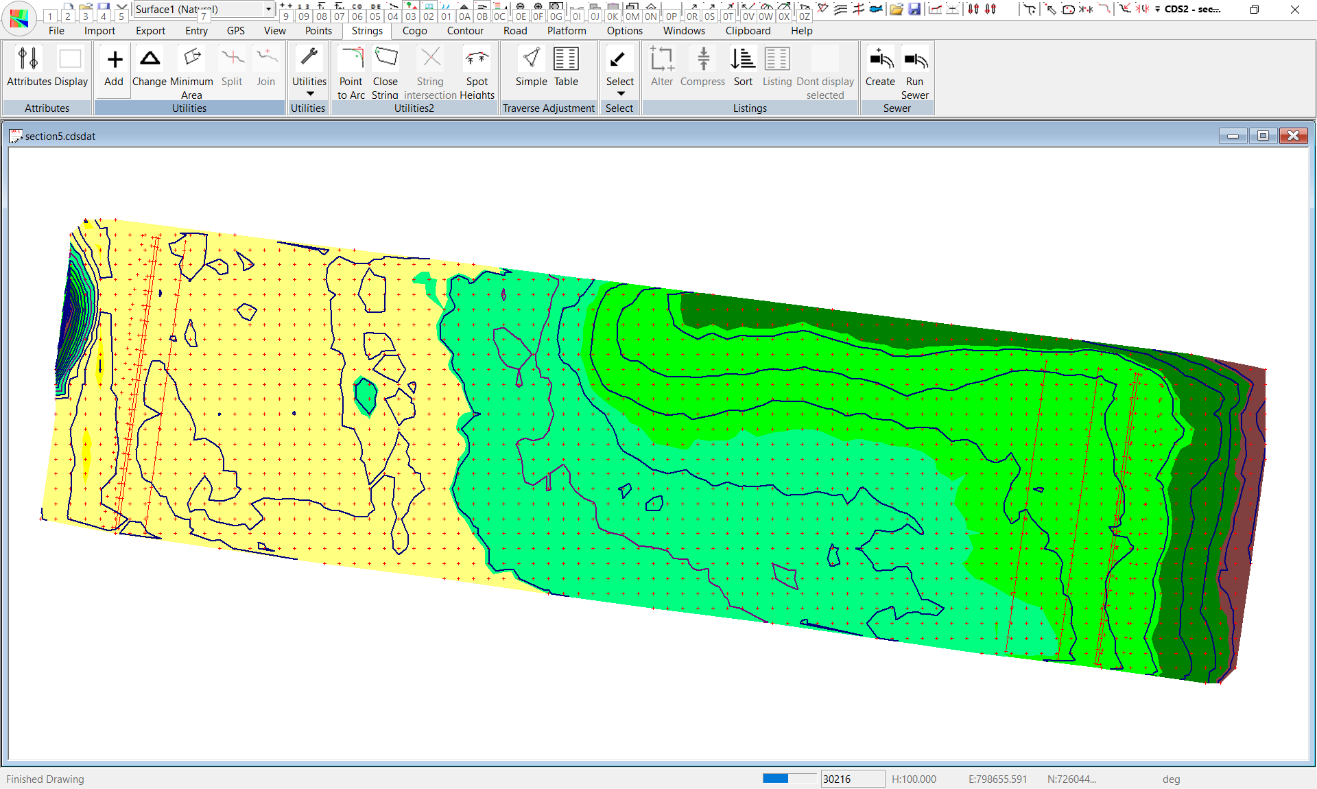
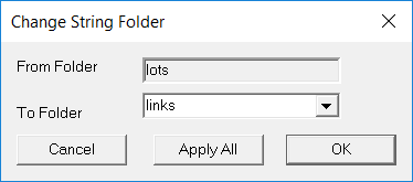
Now go into Ezigrade and open up the job. We need to click in the links. We have a helper function "Fields -> Strings to Links". This converts any strings in the folder called "links" to a section link within Ezigrade. So at this stage you could open up CDS and select the three strings; left edge of section, right edge of section and sill then copy and paste and change folder to links. As per paste below:
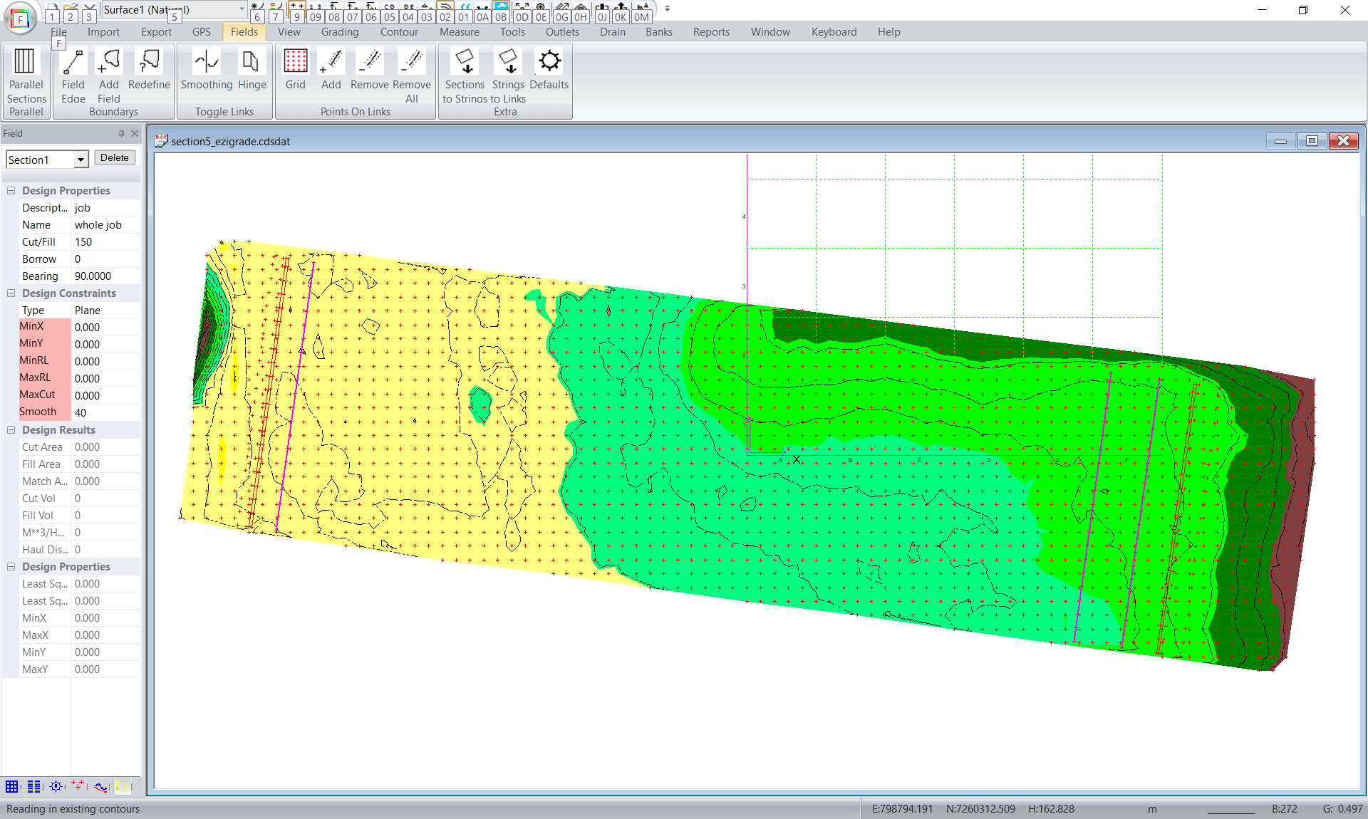
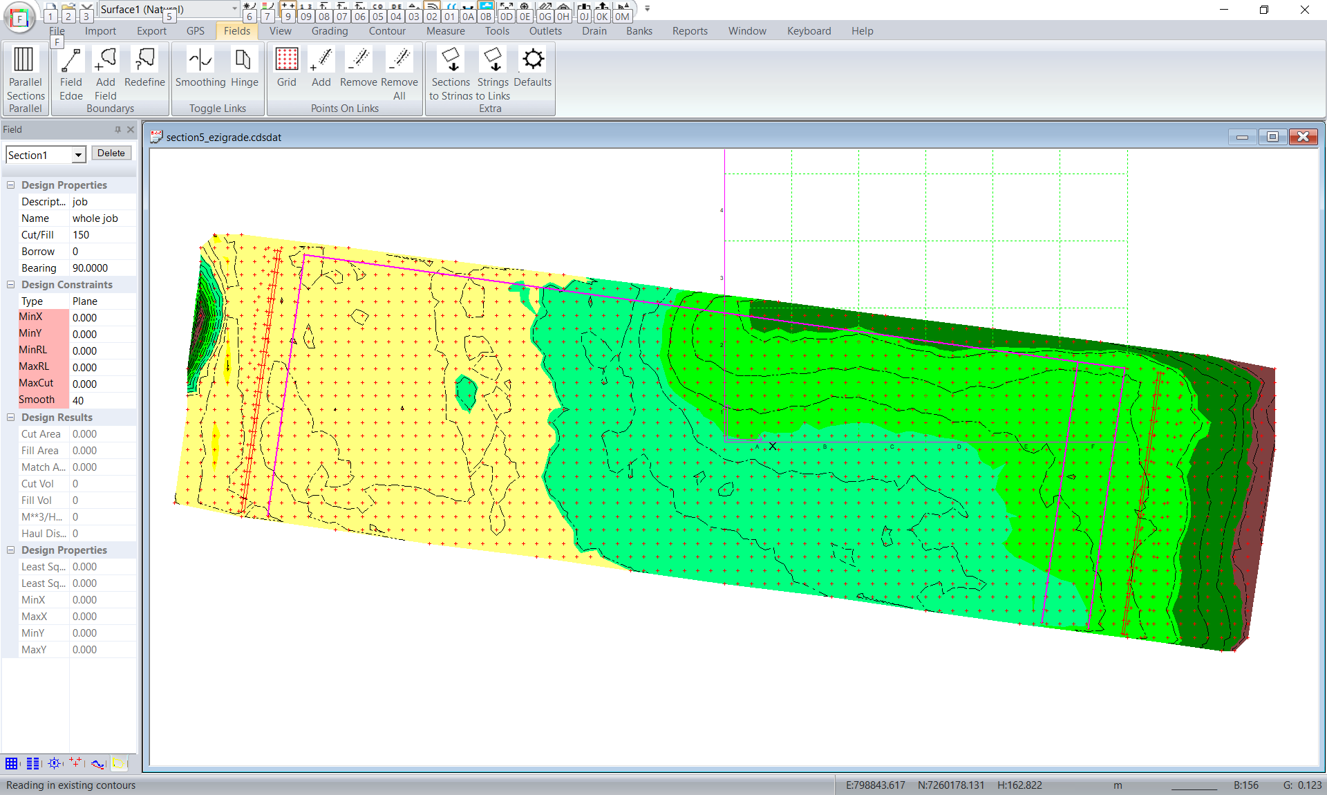
Now go back into Ezigrade and run the Fields -> Strings to Links menu item. We get the 3 links as shown in purple below. We haven't got any sections.
We now need to click in sections along the top and the bottom. Click on Fields -> Field Edge and click in the two northern edges and then enter to finish.
Ezigrade may give a warning that it cant create a section. It try's to help but here there is nothing to do so ignore it. Now click in the southern edge and hit enter to finish.

Ezigrade again try's to create a section but creates wrong one here. No problem. Left click on the 4 left most links to select and then click on Fields -> Redefine to make section1 the left section.
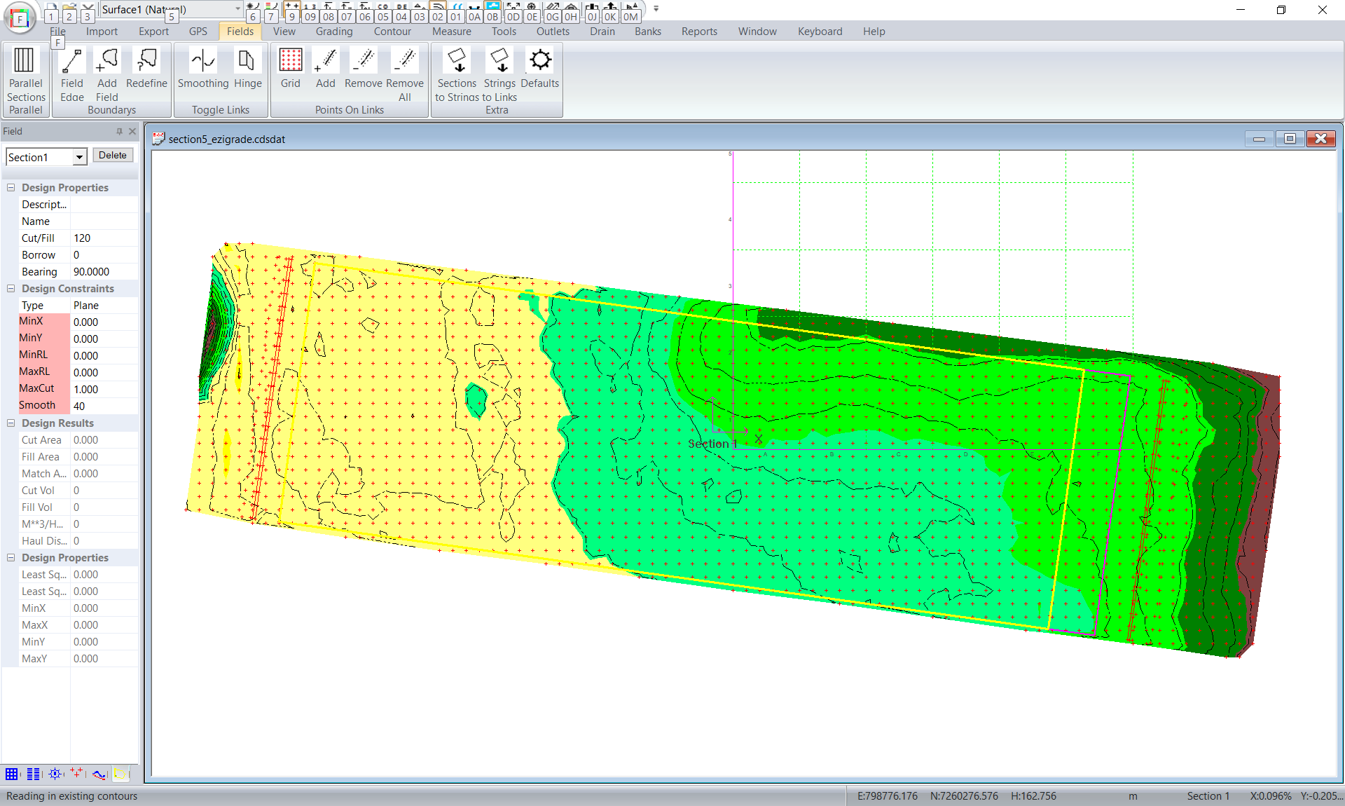
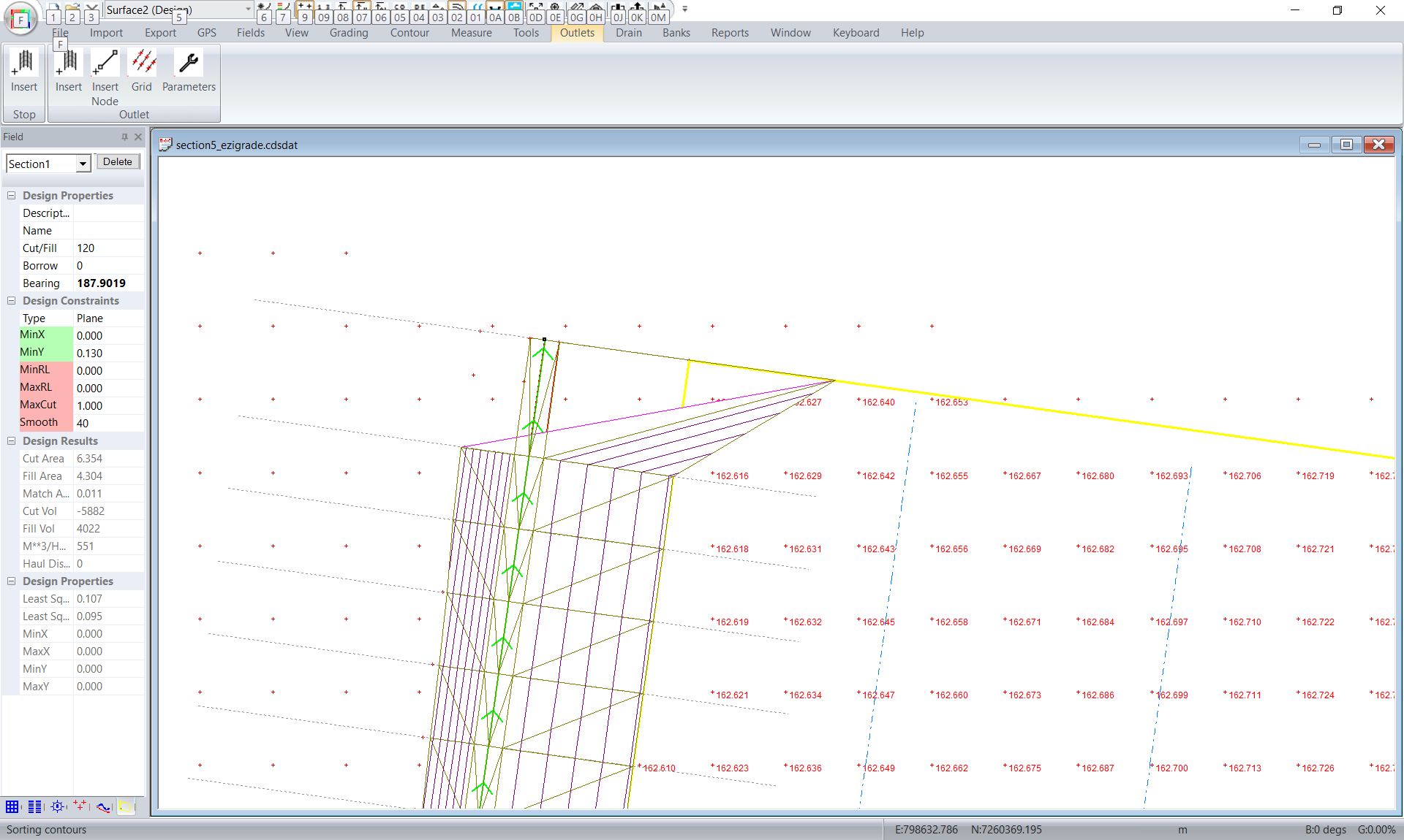
We now need to create the right most section. Left click on the 4 links to the right and click on Fields -> Add Field. We now have two sections. You should now left click on the axis withing section1 and rotate it to the Y axis is running paralel to the section. Repeat for the sill. If you want to be exact to should go back into CDS and calculate the bearing exactly and type it into the "Bearing" field. In this case it is : 187~54'07" ie 187.9019444444
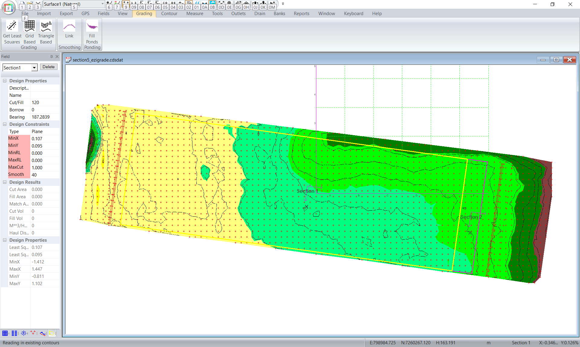
I adjusted the bearing in both sections.
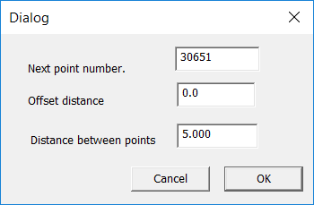
Now we need to hinge the two fields together. Otherwise the heights will not match. Left click on the section link between the two sections and then click on Fileds -> Add Points. We are adding some points along the link. Set offset to 0.0 and click OK.
Make sure the link is still selected and click on Fields -> Hinge. Now hit escape and we should have a grey link here.
In the Field section at the left. We have been told that section1 needs to have a Y grade of 0.13% so in the Field panel to the left make sure we are using a plane and Y is set to 0.13 and X is set to 0. Repeat for section2. Section 2 is flat in Y direction so set this to 0.0 and X to 0.0.
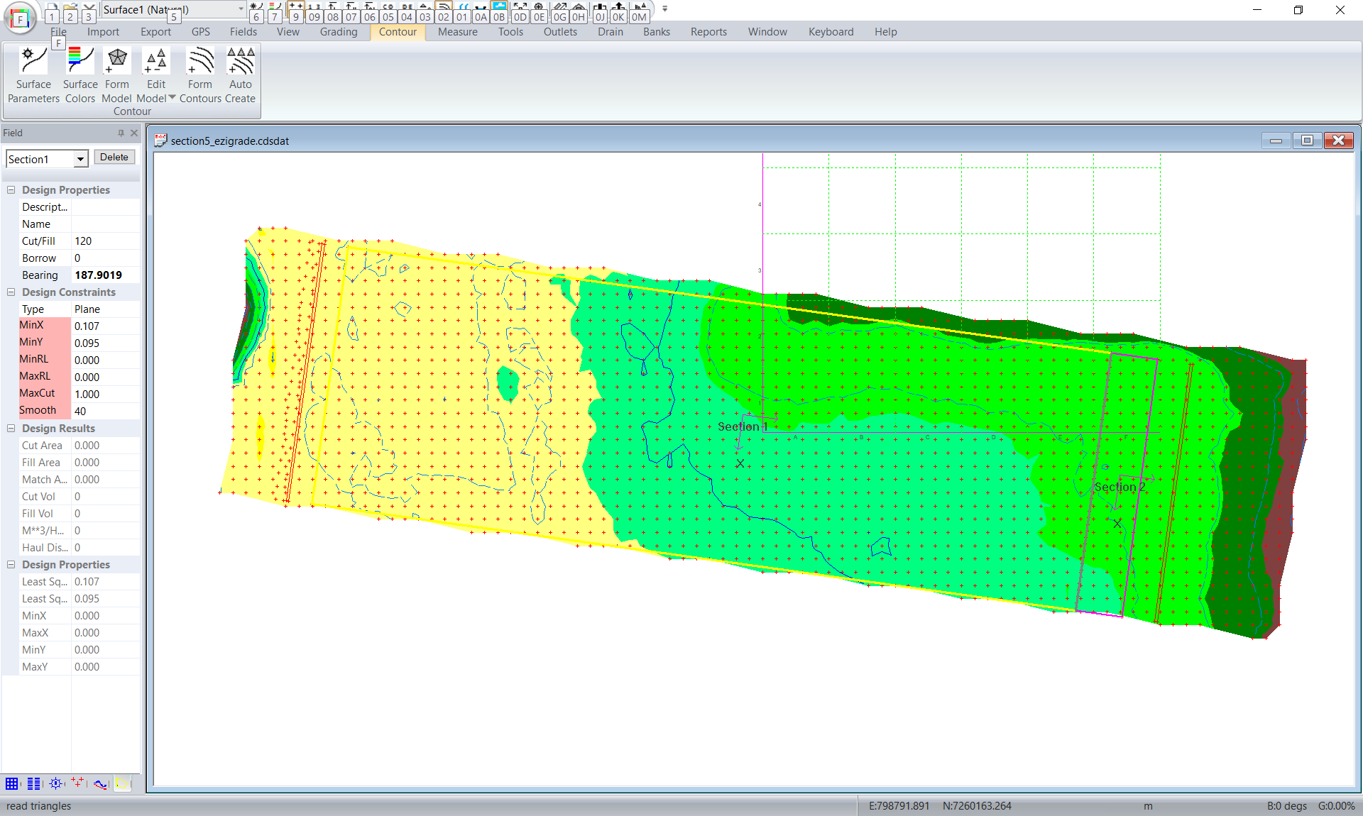
Now click on Grading -> Triangle Based. Here the grading disn't finish and we get an error that the model is INFEASIBLE. ie it is mathematically impossible to get an answer.
What is happening here. In this case we have two planes that match along there length and both there X and Y grades are set. If you just think about section2 - we have three constraints a line and two grades but In this case Ezigrade can only adjust the grades. It should be possible however the bearings of the two sections needs to be correct and the dividing link needs to be exactly at 90 degrees to the bearings. We probably have a mismatch in the 9th decimal place or something. If you cant understand this try drawing it out but change the bearings of the two sections slightly. You will see we cant get a match.
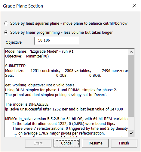
If this happens it means we need to relax our constraints somewhat. In this case we want Y to be flat and edge of sill to match the main section. Make the X constraint red so it is not used and try it again:
We now have a solution and section 2 is still flat.
Designing the drains
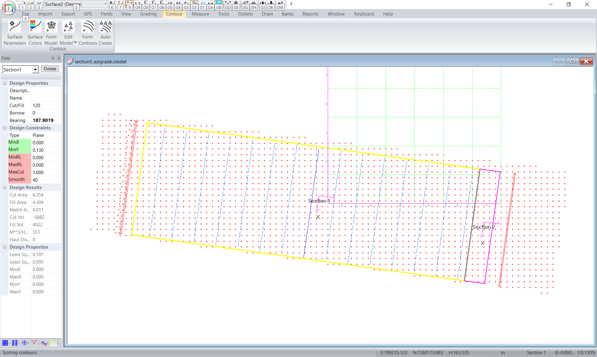
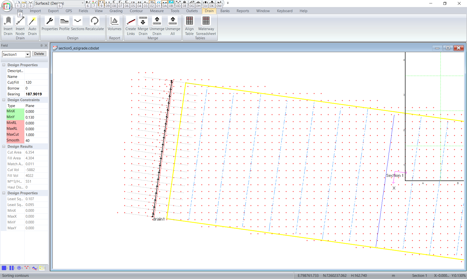
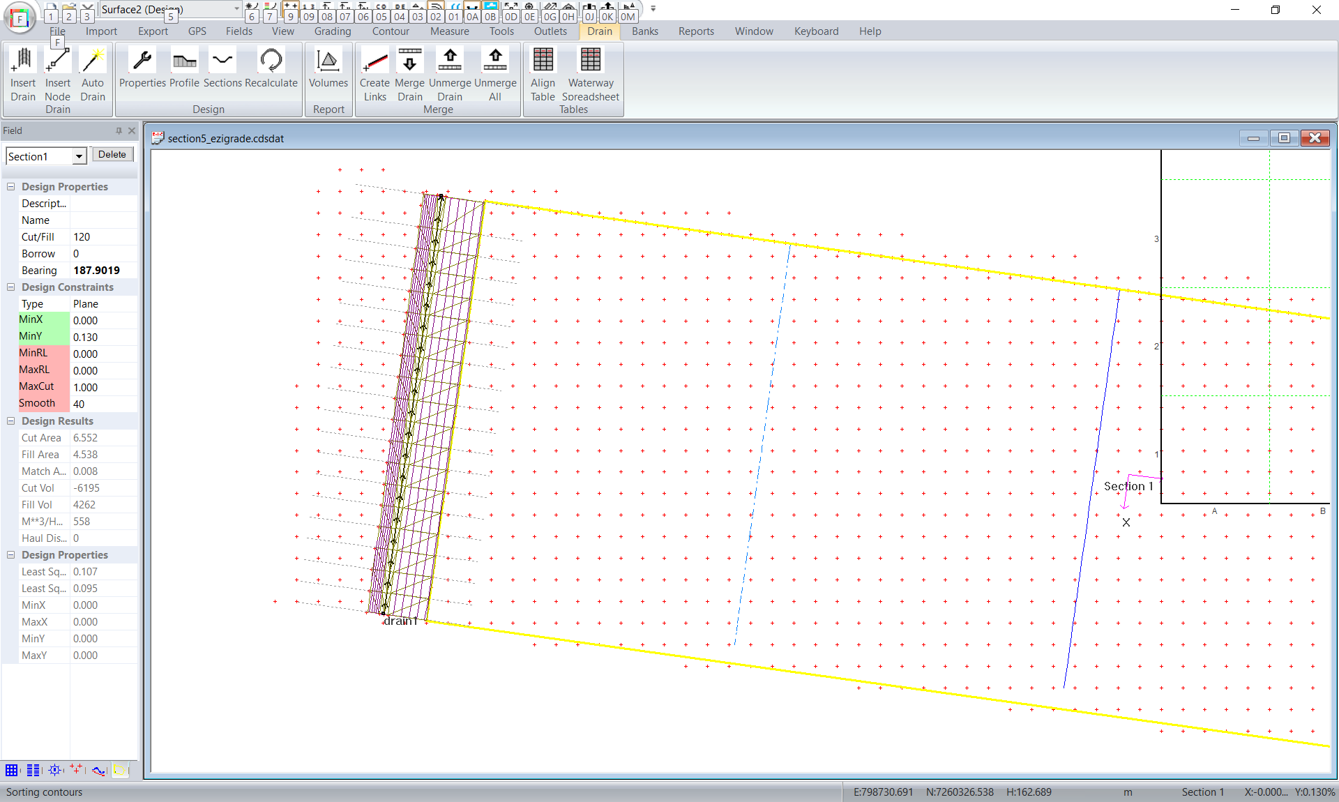
We now need to put in our two respective drains. We will start with the table drain. At present Ezigrade doesn't have a helper function to make a drain follow a CDS string. However in this case we have entered a line so that we have something to follow. Click on Drain -> Insert Drain and we draw in a drain along the center of the table drain. I would draw it south to north so we are going upstream (even though the height is constant). You can zoom in and pan while clicking in the end points for greater accuracy.
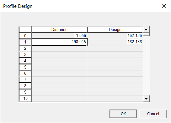
Left click on the drain and it turns green. Now click on Drain -> Profile. Click in a point before and after the natural surface. We are going to fix up the height in the table.
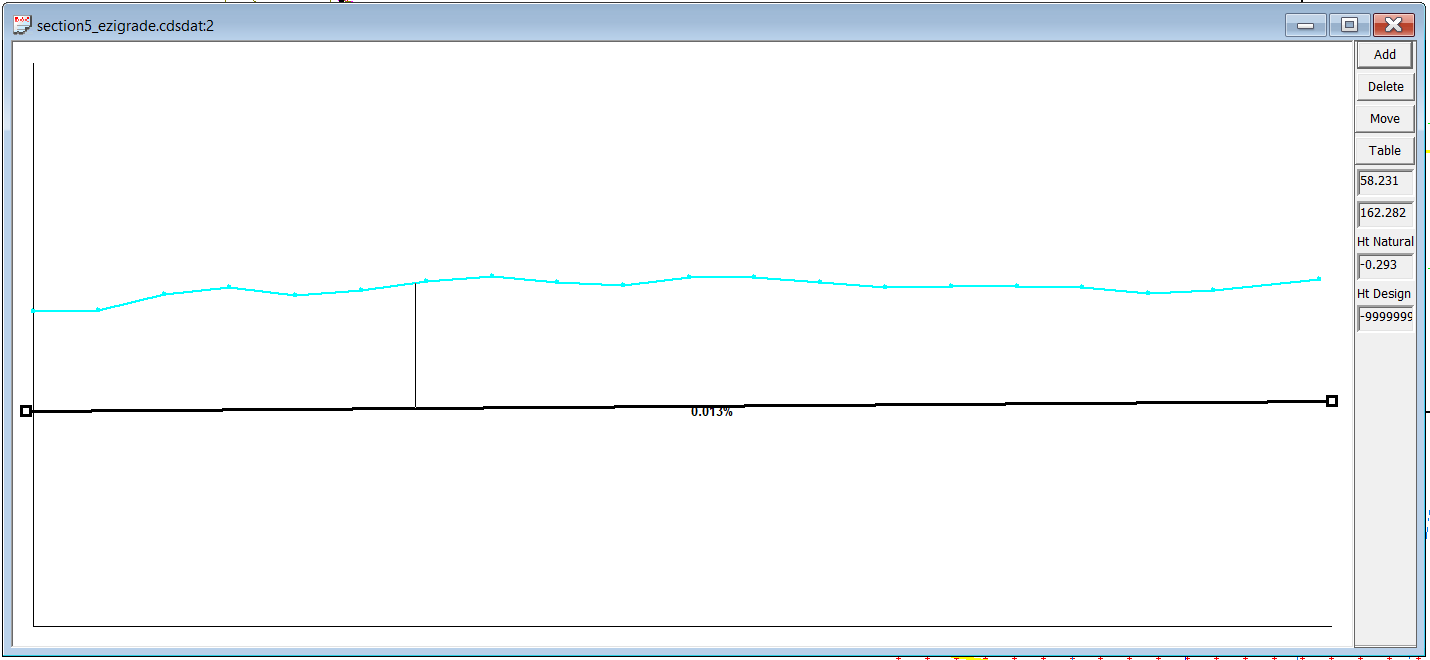
Now click on "Table" button and fill in the heights to be 162.136 and OK.
Click on Drain -> Profile menu item again to remove the profile view.
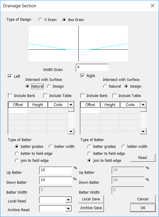
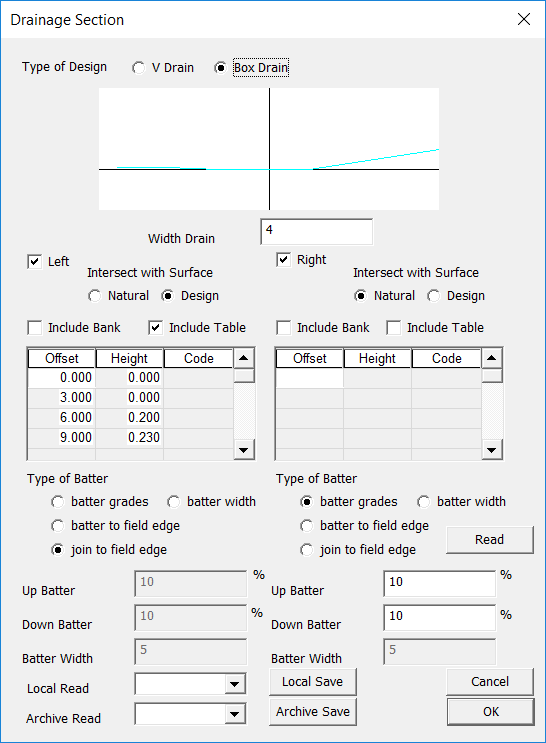
Now click on Drain -> Section. Starting from the top. We want a box drain with a flat bottom. Let the total width of the bottom of the drain be 4 meters.
On the left side we want to intersect with the natural surface. We will be prompted on whether we put out new points as natural or design and then we will say design. We are using a batter slope of 10%.
On the right side we want to intersect with the design surface and we are going to select the "field edge" which is the left edge of section1. Click OK.
Now click on Drain -> Recalculate to see what Ezigrade want's to do.
We can see that the start and end are not intersecting properly. Click on the node and drag it down until it gets a proper intersection with the field edge. We also need to make sure that the points in the section go right to the edge. So select the left and top edge and click on Fields -> Add Points and add in some points at an offset of 0.0.
We now have this:
By inspection the drain looks correct.
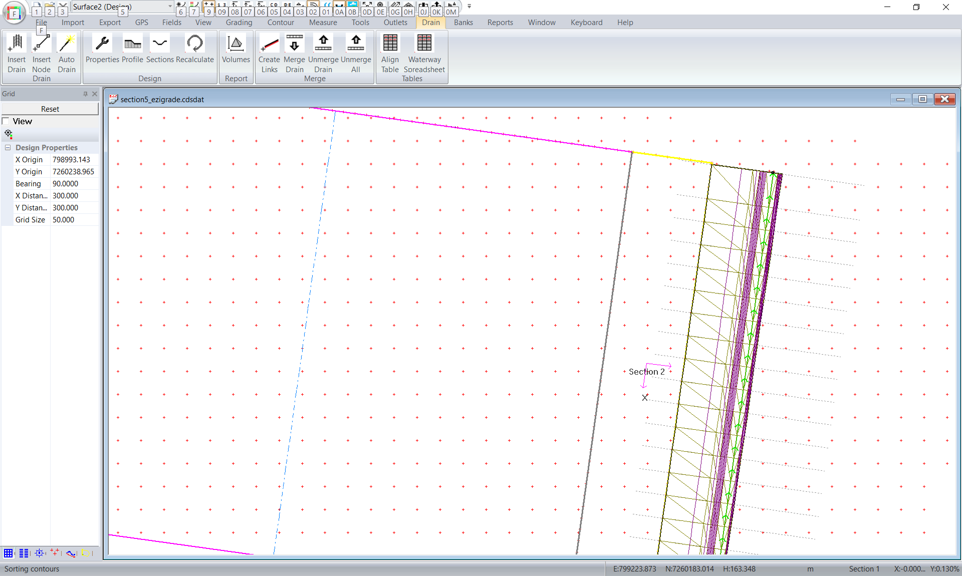
We now need to design the head ditch. Click in the plan view of the Head Ditch drain and create a profile as before. We know the head ditch is to be designed at a depth of 163.113 so do the profile design as before.
The section design for our head ditch is a little different. We want a smooth arc that meets the Sill. This is problamatic as we know the head ditch height but we don't yet know the height at the edge of the sill. We are going to balance the volumes by moving the section/sill up or down. So what I would do is modify the arc into a couple of chords and get a rough balance. We can then add in some more chords later and realizing that the volumes will change slightly but probably not enough to further correct.
We achieve a smooth type edge by using the "include table" option. As mentioned we can add more elements to this to get a better arc.
And if we recalculate we get this:
We are now in a position to check volumes. You can click on report -> pdf and it will give volumes of the sections. Yo can click on drains volume to get the drain volumes. At present we have the following:
cut volume fill volume
sect1 -6396 4253
sect2 1077
td drain -2352 0
hd drain -150 450
ie cut -8898 fill 5780
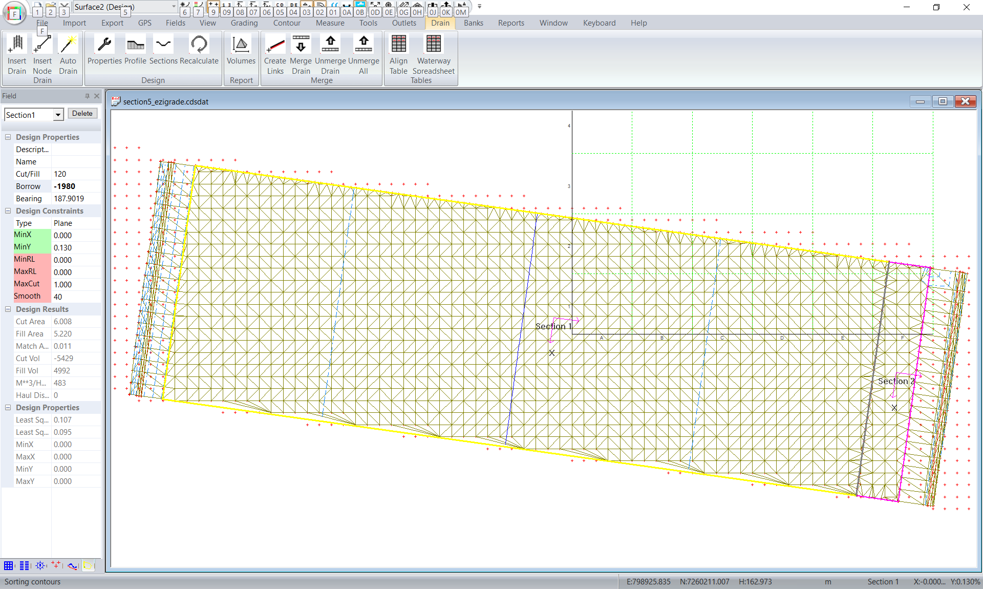
Assuming we have a cut/fill ratio of 1.2 then we have difference = 5780 - 8898/1.2 = -1653. Add in a borrow of -1653 * 1.2 = -1980 Lets add this into the borrow of section1 and redo the volumes.
cut volume fill volume
sect1 -5428 4991
sect2 1181
td drain -2326
hd drain -156 485
ie cut -7951 fill 6657 then difference = 6557 - 7951/1.2 = -68 m**3
This may be close enough. If not repeat the process until you are comfortable with the result. The answer is never going to be exact after the first iteration as the relationship between borrow and total cut and fills is not linear.
At this stage we would go back and change the head ditch template to make a better arc with the new height. We would then recheck the volumes to confirm.
After this we can then merge the two drains. Doing this we have:
Check the volumes by going to report -> pdf and we have total cuts -7644 and total fills of 6238 which is acceptable. It is useful going to measure -> area and draw in an area over the design - hit enter and the volumes are displayed. This is calculated in a different manner so is a good check.
|