| < Previous page | Next page > |
Convert DWG to Field Level II file
In this tutorial we go through the steps that you would follow to convert a design within a DWG file into a Trimble Field Level II Civil Design.
Features that needs to be within the DWG file
When obtaining the DWG from your designer it is important that the DWG supports the following general features and guidelines:
Features in .gps Control Block
I will run through a basic outline of the data in the control block. This gives us an idea of what we can expect out.
Importing Data from DWG
We have been given a DWG that contains a natural surface and two design surfaces. The data is in state plane coordinates and is in zone 2302 Mississippi West.
At present Ezigrade doesn't import a DWG, we need to do this through CDS.
Open up CDS. Before importing the data we need to first create a new job. Use the "File" menu and then "New" option. We are going to call this job "subcell".
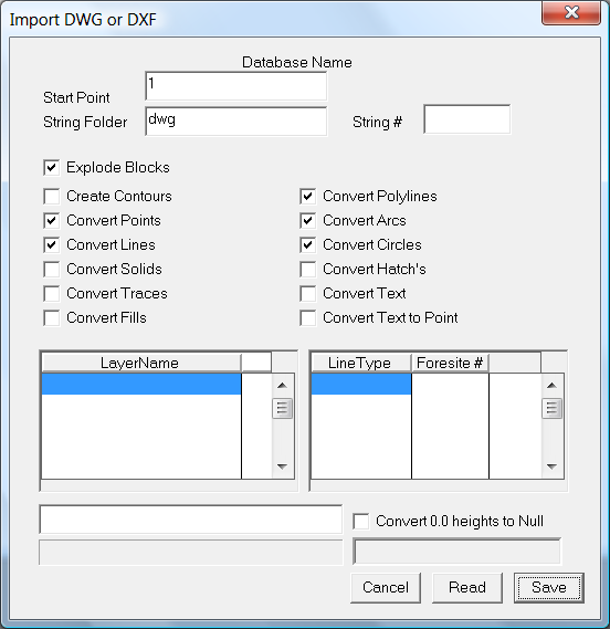
To import this data use the File - Import DWG/DXF menu item. You will get the following dialog. Click on the "Read" button and the DWG is read in. Once the file is read into memory you are given a prompt message. Now click on the "Save" menu.
For each series of 3D Faces you are prompted on whether the surface is an existing surface (natural) or is a as-built (design) surface. If you get it wrong first time through simply run it all again. If you are importing a LandXML file you are also prompted on what type each surface is. The prompt you will get is seen below:
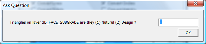
In this example we have three surfaces so are asked the question 3 times. Once the procedure is finished the imported surface is displayed. If you can't see anything type "ze" for zoom extents ( don't type the ")
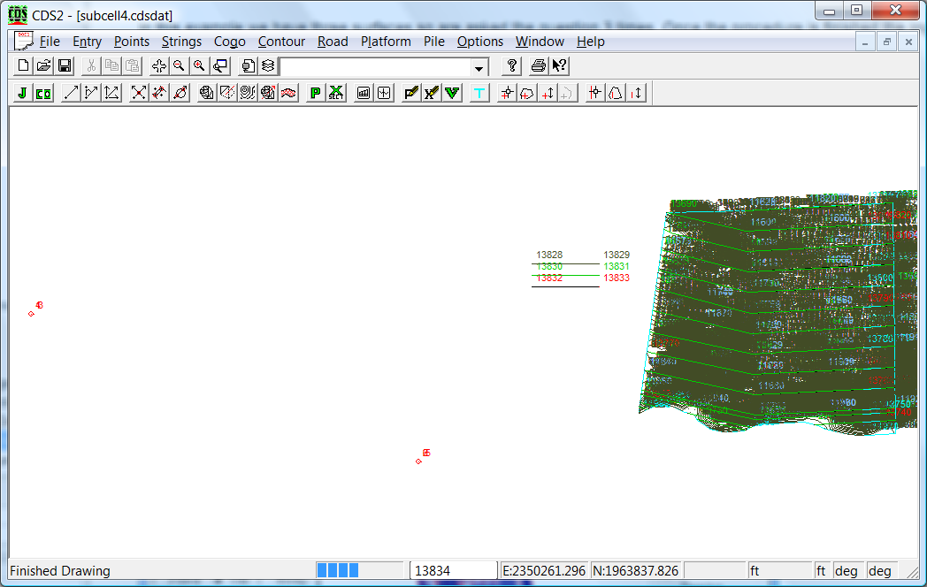
This DWG contains some extranous data that is not really needed. ie The contours which come in as string-lines. In this example we can tell CDS and hence Ezigrade to not display the string lines. However it may be handy to keep the blue string that defines the outline of the job. I suggest that you check the triangular surfaces before continuing.
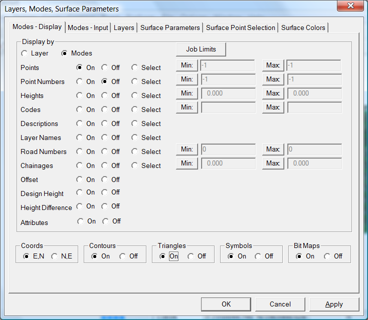
First click on the Modes icon button. It is to the left of the Layers Icon. It is the 11th icon from the left on the first row of icons. I suggest that you change the Display to by Modes and then leave "Points" displayed but probably don't to display "Point Numbers". Further down make sure the "Triangles" radio button is "On".
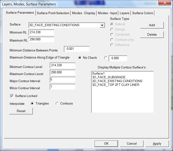
To change the surface to display, click on the "Contour" - "Surface Parameters" button and look at each surface in turn. It would also be useful to create some contours as a check of how representative the surface is. For example change the surface to "3D_FACE_EXISTING CONDITIONS". I would also suggest changing the contour intervals to 5 and 1 respectively. The default values are too close.
To create contours use the "Contour" - "Calculate Contours" option. You should have the following. If you are unsure here on what you are doing I suggest you re-read some of the introductory tutorials at the start of the CDS2 tutorial manual.
We have to tell the software which point is the "Master Bench". To do this we need to set the code of the point to MB. Within CDS right click on the appropriate point and change the code as below:
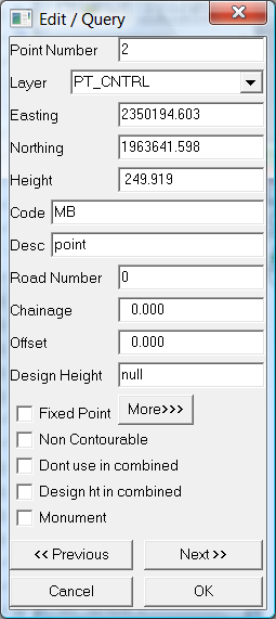
Now click OK.
We can now open the job within Ezigrade. From the "File" menu click on "Close and re-open in Ezigrade".
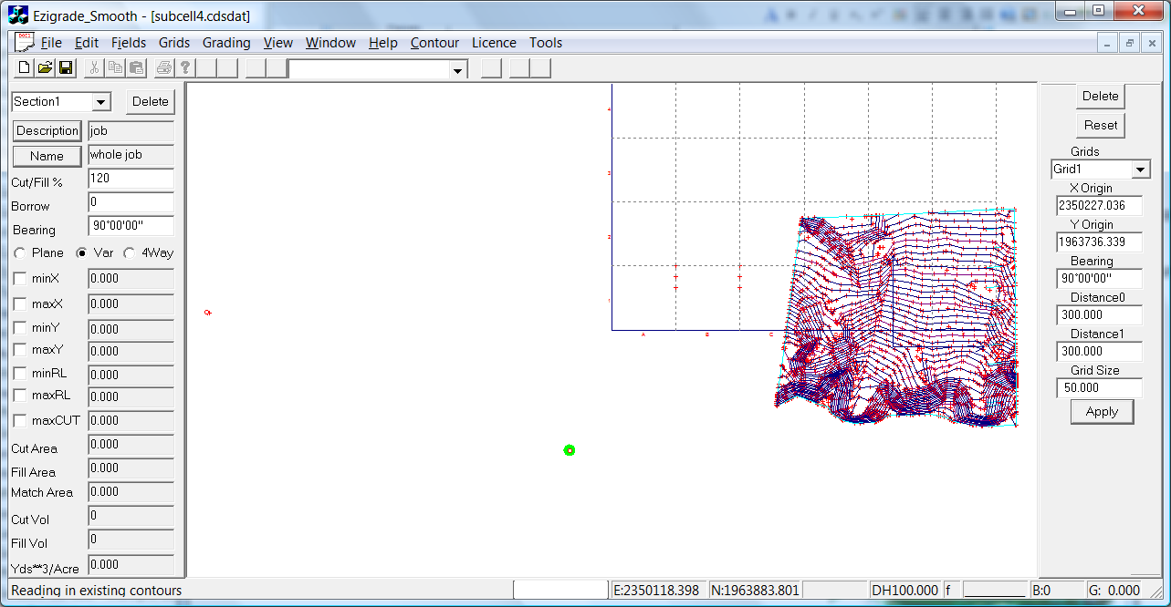
The Master Bench is shown as green dot. If you need any additional bench-marks displayed then back in CDS you need to set the codes of additional points as BM1,BM2 etc
There is really nothing else to do except export the Trimble data directly. From the "File" menu click on the "Export Trimble Machine (*.gps). A dialog is displayed which creates the file directly.
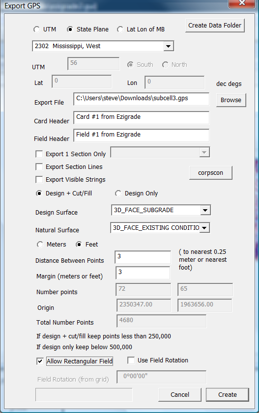
In this example I suggest that you fill in the dialog as above. In this case we have the data in State Plane coordinates so make sure the state plane radio button is set. From the drop down menu select the "Mississippi West" option. If you don't know the coordinate system we suggest that you set the format to "Lat Lon of MB" and then enter the lat and lon of the Master Bench in decimal degrees. Click on the "Browse" button to create a new "Export File". Select the appropriate Design and Natural surface. Further down you need to set the distance between points in the grid and the appropriate margin. Keep track of the total number of points that will be generated. Normally the closer together the better that keeps the number of points below the maximum that will fix. The .gps file format is a very old format that is a fixed size.
If you wish to rotate the field click on the "Use Field Rotation". The rotation will match the grid. Set this up before going into the dialog if necessary. Please be aware that some of the earlier versions of Field Level II does not support field rotation; or so we have been told.
Once happy click the "Create" button and the .gps file is created.
As far as we are aware Trimble doesn't make available any way to actually check the .gps file other than physically putting it on the tractor and being close to the action.
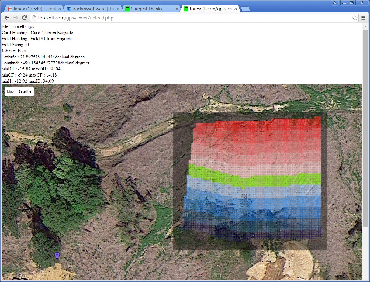
As a way of hopefully reducing the chance of making a boo-boo we have created our own online viewer so that you the designer can check and also the land grading contractor:
Go to http://foresoft.com/gpsviewer/browsefile.php
If you run this you can see our design as follows:
 |