| < Previous page | Next page > |
Pivot Design
This tutorial describes the process of creating sections around a pivot point. This is for when we wish to force the water to flow around the pivot. For example you may have furrows with vegetables or as in this case we have a Turf farm design. In this case when the turf is established then the water can flow off the field. In this case we are going to design a drain across the center of the design. However when they harvest the turf they harvest around the pivot and leave a thin strip of turf. The next crop grows back from these strips. However the strips left stop the water flowing cross-wise so we need to make sure that the water will flow around the paddock into the drain.
If you simply need the water to flow and not around the pivot then please do not follow this tutorial.
Our design brief is to grade around a pivot. We are going to have an access road running North-South and a drain running West-East. Ezigrade doesn't support circular arcs in sections. However the more you split up a circle into chords then the more it approximates a circle.
In this design we are splitting the job into 4 quarters. Between each quarter we are going to have either a 5 meter wide road or a 5 meter wide drain.
If we look at the job we have this:
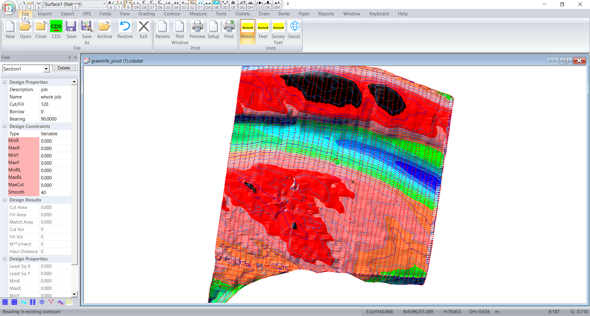
The center of the pivot is point1. The pivot radius is 290 meters. The first section is to run at 10 degrees. In this design we will put in 20 sections so each section is 18 degrees around. We need to define an inner radius to avoid mathematical numerical problems. Most of the entries should be obvious. The Margin entry is slightly different. If you enter a single "0" then all the field margings will be zero. If you entered "1" then every section will have a margin of 1. Otherwise you can specify each margin seperately. The first entry is the margin before the first section, Subsequent values are the margin equally shared between sections and the last is the margin after the last section. So you would have one more margin than sections.
The angle is the included angle of the section. If you are going all the way around then the number times angle should equal 360.
If we click on Fields -> Pivot sections and we fill in the dialog as follows:
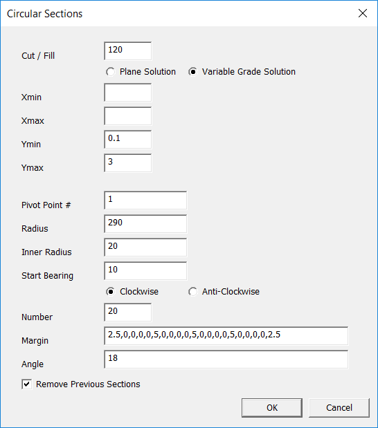
Click on OK and see what we get:
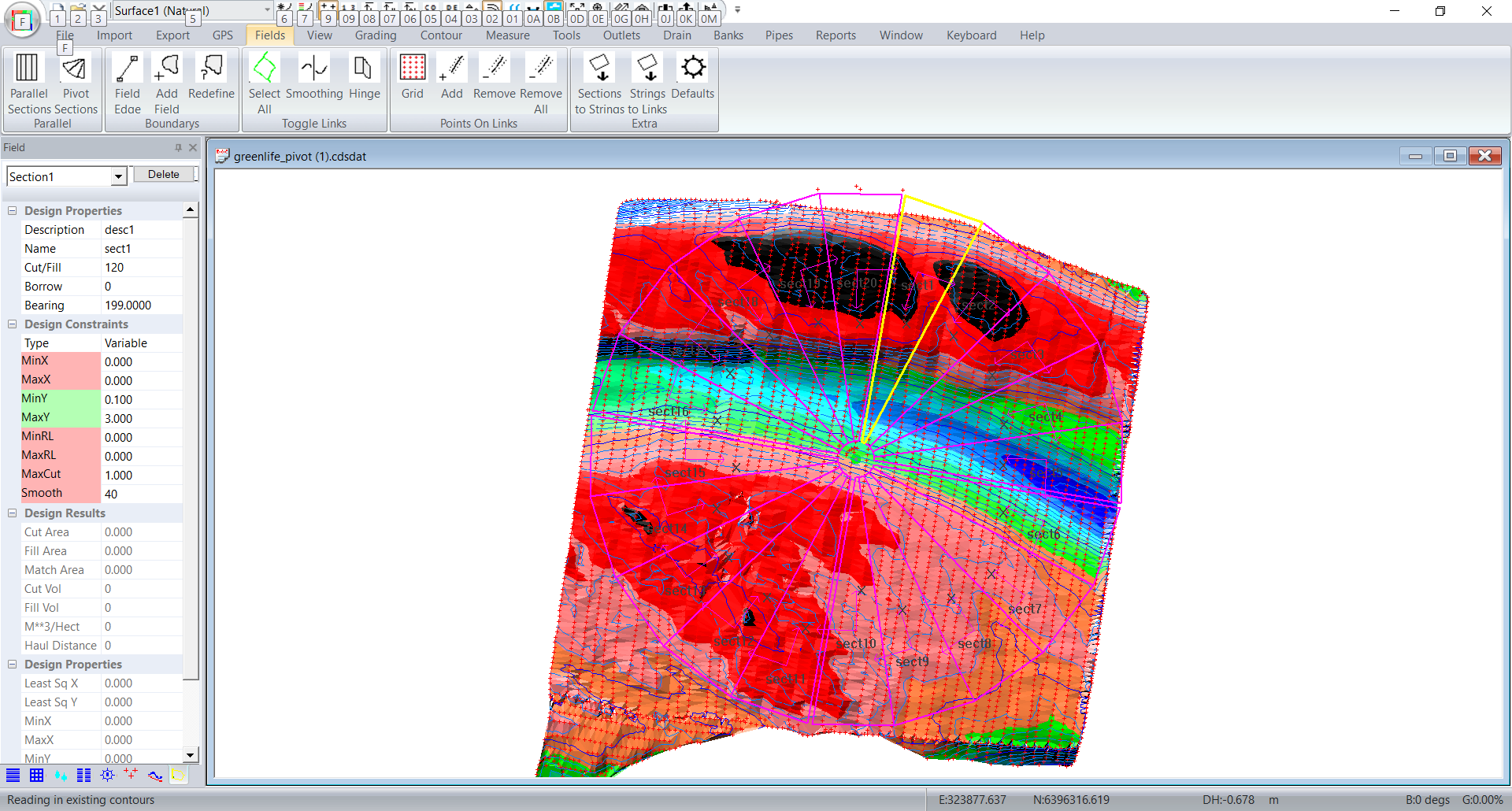
Make sure the margins are set for the road and the drain. If not simply repeat the process. The original design will be overwritten.
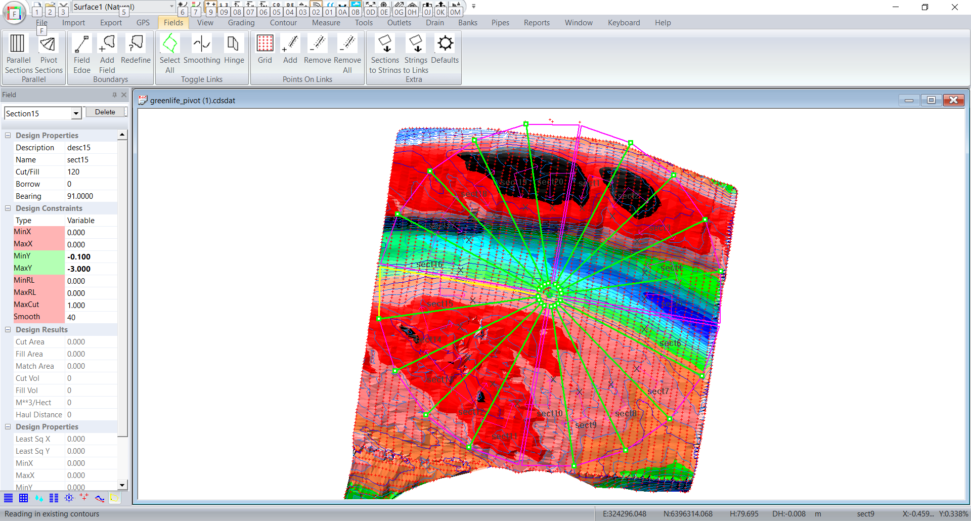
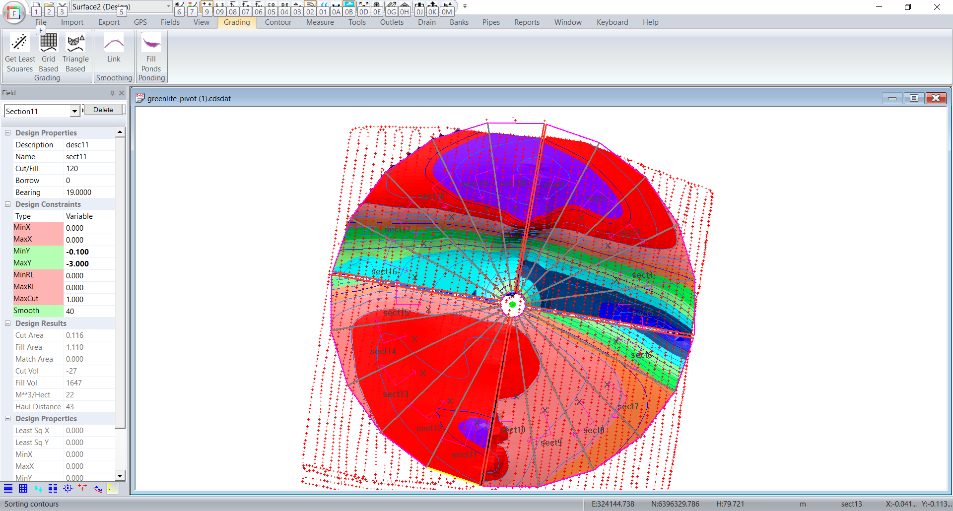
In our example we want sections 1~5 to drain clockwise. Sections 6~10 drain anti-clockwise. Section 11~15 drain anti-clockwise and Sections 16~20 drain anti-clockwise.
So for sections 1 ~ 5. The Y axis is pointing clockwise. If we want the water to flow this way then the Y grades need to be negative. So for sections 1 ~5 I have set the MinY -0.1 and MaxY to -3. Sections 11 ~ 15 are set the same. Sections 6 ~ 10 and Sections 16 ~ 20 are set as minY 0.1, maxY 3. These values will be set up correctly from the dialog.
So go and set 1 ~5 and 11 ~ 15 correctly.
In this case we want the sections in each quarter to hinge together. Click on the links that we want as hinges.
Now click on Fields -> Hinge and then press the escape key. These links will go grey.
We also want to put in extra points along the hinges and the outer edges. In fact all the links. Click on Fields -> Select All (Toggle Links) and all the links turn green.
Now click on Fields -> Add (Points on Links) and we filled in as follows:
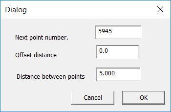
and click OK.
Now click on Grading -> Triangle Based
The first time we ran this we wanted a smoother result. We went in and set smoothing fro each section. We also set the Fields -> Smoothing links at each quarter start and end link.
We then get. If you look at the contours you will see that:
The greater the number of sections then the closer it approximates an arc.
One thing to watch for is if and when Ezigrade flags an "infeasible" solution. ie a solution that is mathematically impossible. Look at the simplified case below:
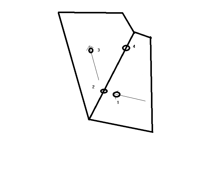
In this example we have water flowing clockwise. The water is flowing through point 1, hits point 2 and then bends around and flows to point 3. Lets assume that we want the cross-grade to be zero. The height at point 1 is 5m. It drops to 4.8m at point 2 and then drops further to 4.5m at point 3. Now we want the cross-grade from point 1 to point4 is zero. So the height of point4 is 5m. If we go around to point 3 this tells us the the height at point4 is in fact 4.5m. In this case point4 is in both sections. We can't have different heights at the same physical point. ie the solution is mathematically impossible. In practise you will need to relax the X cross grades so that the solution is feasible.
In practise don't specify cross-grades. Then have a look at the cross grades around the job. Move the mouse and look at the bottom right of the screen. This will give you an idea of how much to tighten up the cross-grades. You can do this until you get an infeasible solution and then back them off again.
|