| < Previous page | Next page > |
Grading Menu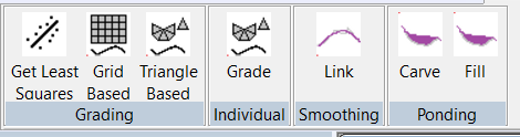 Get Least Squares
This option calculates a number of appropriate parameters applicable to each section. It fills in these values in the appropriate sections in the info bar to the left of Ezigrade.
Also if the min/max grades for grading constraints aren't set then these values are changed to the best fit plane. This is a useful guide if you wish to set the slopes when doing a plane design. You often do this when you wish to match neighbouring planes.
Grading - grid and triangle based
We have supplied two different methods of creating the graded output. They are grid based and triangle based. The legacy method used since day1 is based on gridding the data and working on this. The triangle based method works directly upon the triangles which is a better representation of the base job.
We suggest that you use "Triangle Based". This is left here as a backup.
Here are some plus's and minus's of the two different methods:
Clicking on the Grading (grid based)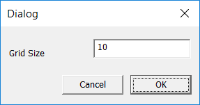
Please note that if you are doing plane design's only then you can simply click OK. Otherwise set a grid size. If you wish to smooth between planes then the smoothing options can be used.
Clicking on the Grading (triangle based)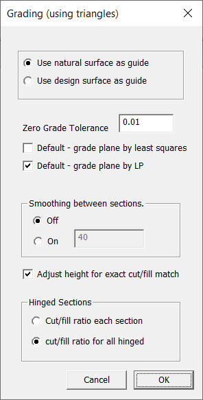
We are given the option of using the existing natural surface as a guide or to use the design surface as a template. So we use the triangles in either the natural or the design surface. If we are starting a new job and we haven't an existing design surface then Ezigrade automatically forces you to use the natural surface as a template. If there is an existing design surface and you have either a drain, outlet or breaklines then Ezigrade will default you to using the design surface as a template. If you have a design surface but no drain etc then Ezigrade will default to using the natural surface triangles.
Here are some relevant thoughts:
Zero grade tolerance. The linear programming routines like a bit of variation. The zero grade tolerance actually says that if min and max grades are the same then allow them to vary plus or minus 0.01%. For more critical applications you can set this to 0.001% for example.
If you are doing planes of best fit then tick the appropriate tick box for either doing a "least squares" solution or alternatively a "linear programming" solution. The least squares solution calculates the plane of best fit by minimising the sum of the least squares difference to all the points in the job. The linear programming solution consists of putting all the points into a mega-big matrix and manipulating it to mimimise a function that approximates the total cut volume.
Or for a non-technical difference. The least squares is quicker but not as accurate. In practice the difference is not that much and probably not worth worrying about.
Smoothing between Sections
I generally suggest that this option is turned off. It can help merge fields together that are not hinged. However we would normally suggest that if you want sections to match along an edge then you make the Field link a hinge.
Adjust Height for Exact cut/fill match
Leave this turned on. Once grading is done every section is moved up and down to match the cut and fill. Some constraints automatically turn this option off. For example fixed height points etc. In this case you could tweak the cut/fill ratio to fine tune things manually.
Hinged Sections
When we have sections hinged together we can specify how the cut/fill is organised among the sections. The default is to share the cut/fill among all the sections joined together. However you also have the option of forcing the cut/fill for each section individually.
Grade Individual
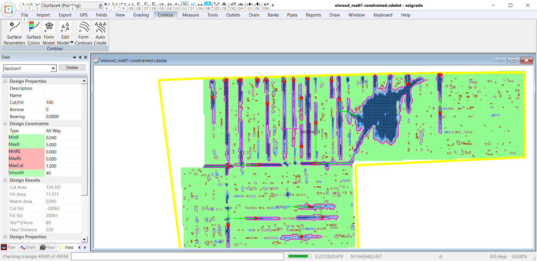
With large jobs with multiple sections, it can take a while for the whole process to run through. With this option you can grade a single section only and look at the results for this section only. Go to another section and check this as well. However you still need to go back and do triangle based grading on the whole job for a result.
Link Smoothing
Once you have run the triangle based grading you may wish the joins between sections to be smoother. You could then run this option and check for an improvement. If you are not happy with the result then rerun the triangles based grading.
Ponding
When we have a ponding area. There are two ways of stopping the water pooling together. We can fill in the pond or we can carve out a path to let the water out. The first option can control what option we want for each pond in the job.
Carve
Click on the Carve menu item. It is likely that you will get a message such as:
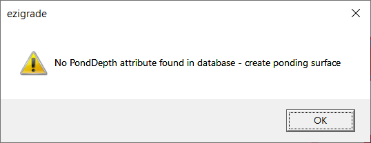
For this option to work Ezigrade needs to know where the ponds are. In Ezigrade you can create a ponding surface. At present you need to do the following:
When you run the option Ezigrade needs to do some background processing and a table is displayed.
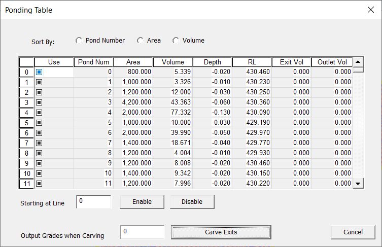
With a pond it is generally better to carve an exit for a pond with a large volume. However you would normally want to fill a small pond that would involve a large volume to carve an exit. With this table the user has a method of defining what they are after. Click on Volume to sort by volume. You can then enable or disable ponds. If enabled we do a carve. If not we do a fill and the pond is ignored.
Once you have defined what you are after hit the "Carve Exists" button.
The display is still being worked upon but you have something like this that shows the ponds and the exit. The red dot is the deepest point and the green line is the cheapest path to carve
You can redo until happy and then do triangle based grading.
Fill
Clicking this will fill in ponds without running triangle based grading etc. Normally you would incorporate this into the triangle based grading.
Smoothing Value.
After the field is graded so that either a plane or constrained grades are produced you have the option of smoothing the surface. This is a bit like running a fine grader over the surface. Smoothing the surface is a good idea as it reduces change of grades and leads to better water run-off.
The smoothing is based on least squares. The "smoothing" distance is how far to look to pick up points to be used in smoothing.
The larger these values are the smoother the surface. If you make the values large in relation to the field then you will basically end up with a plane. Make them both small and there will be little effect.
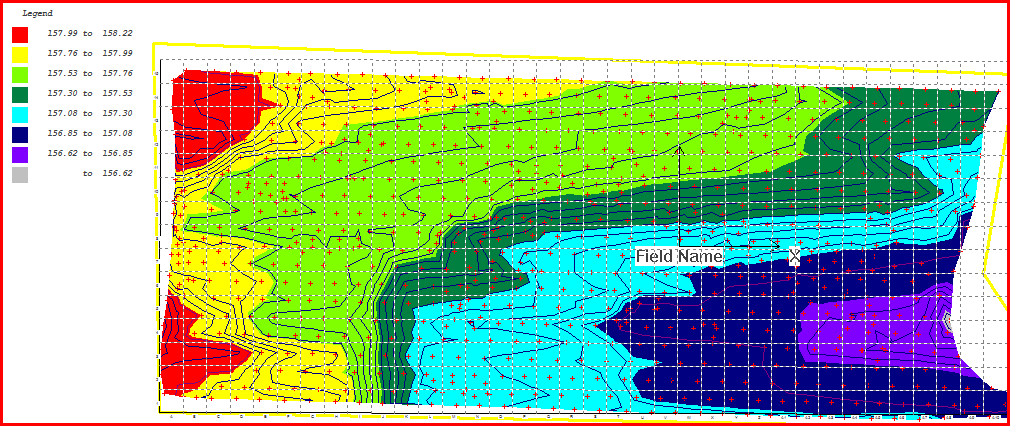
Here are some sample's from a real job and shows the effect of these values:
When doing a design like this you can trade off the smoothness of the finished surface with the amount of dirt that needs to be removed.
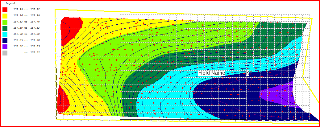
Example1: No smoothing.
Cut Value -10656
Fill Value 8881
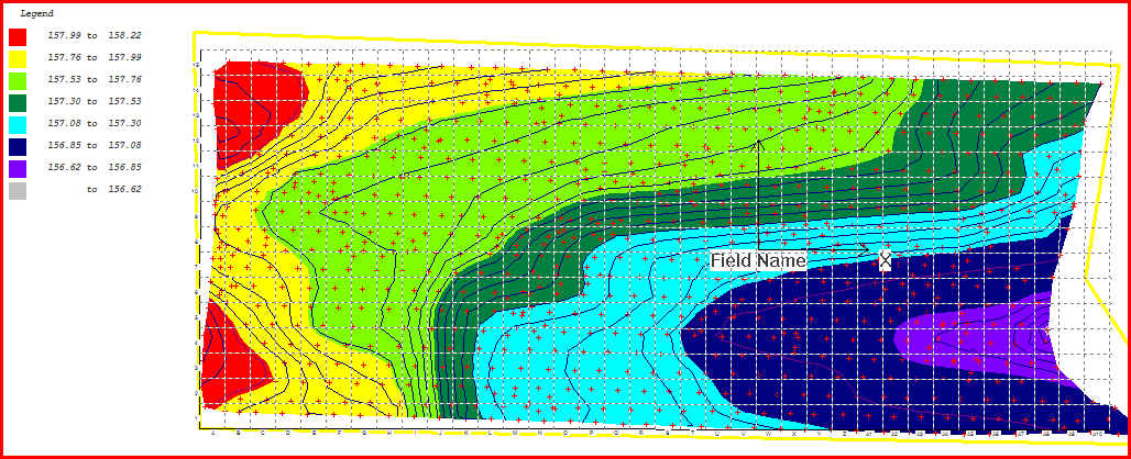
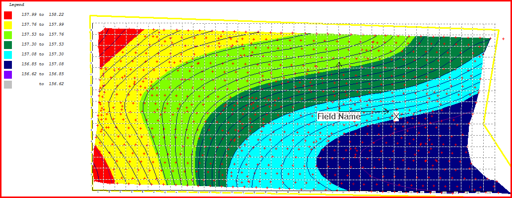
Example 2: smoothing values of 30
Cut Value -11154
Fill Value 9296
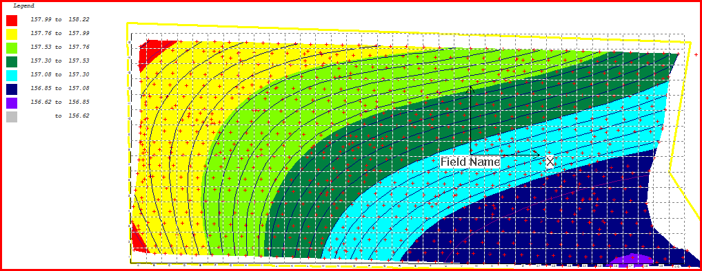
Example 3: smoothing values of 40 and 60 respectively
Cut Value -12008
Fill Value 10007
Example 4: smoothing value 120
Cut Value -13219
Fill Value 11015
Example 5: smoothing value 240
Cut Value -14400
Fill Value 12001
 |