| < Previous page | Next page > |
Designing a Ring Tank
The Drain routines allow us to also design banks etc. A bank is just an inverted surface drain, where the centre of the design is above the surface and you would normally batter down to the appropriate surface.
In this example we are going to show you how to use the drainage routines to design a ring tank. A ring tank consists of a bank designed such that it holds water; normally as a farm dam.
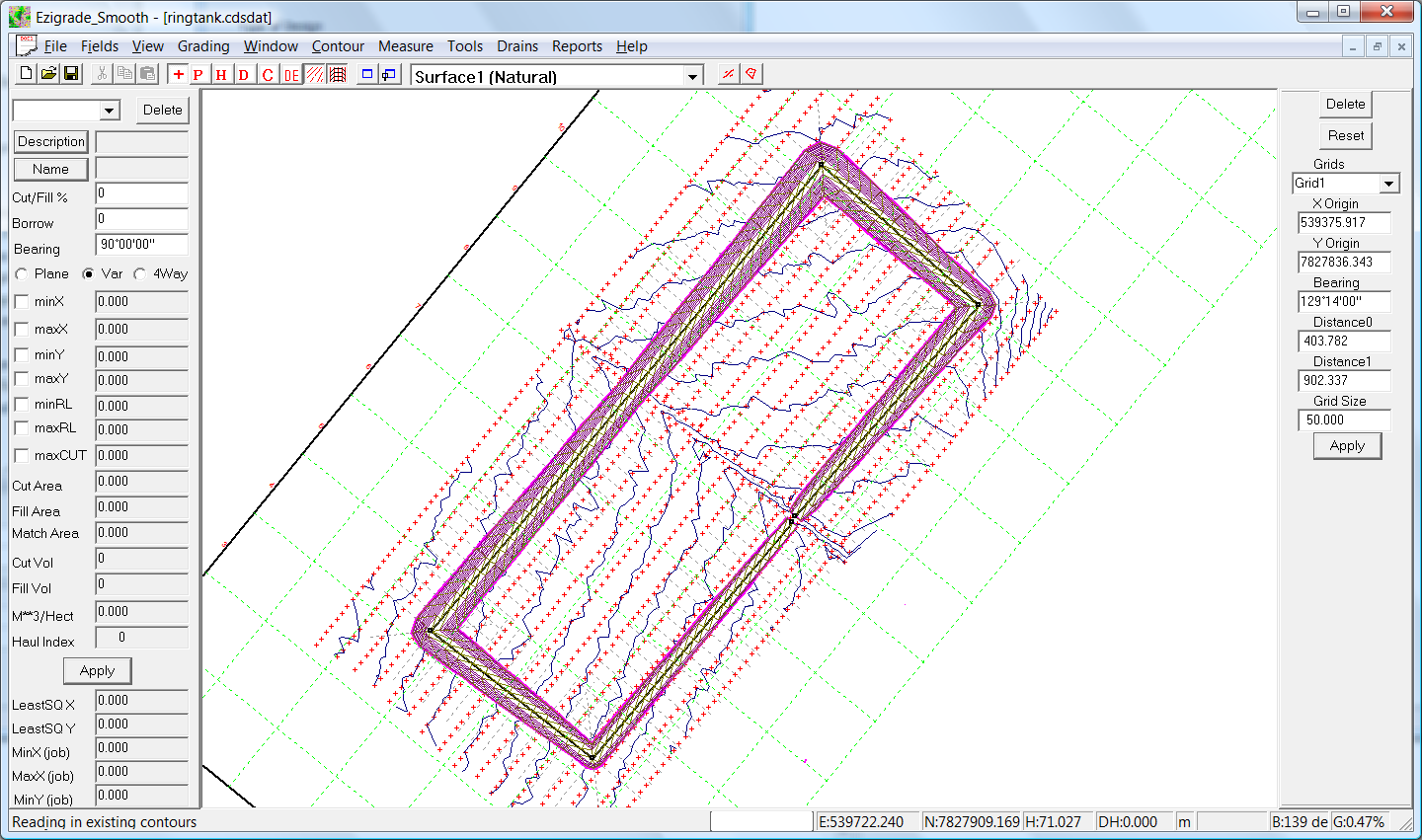
We are starting with the following natural surface.
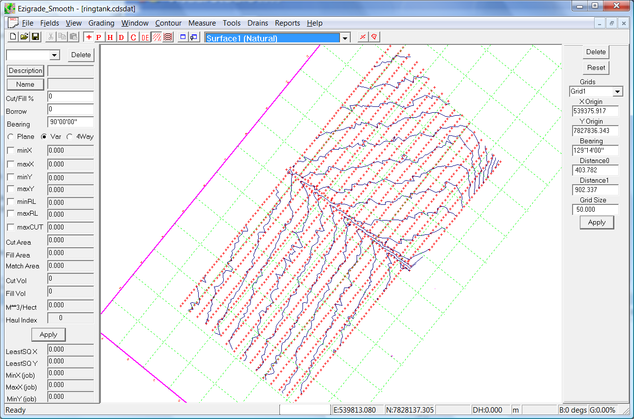
There is an existing drain running through the middle to the North West. We are going to design a rectangular shaped structure that holds water. The first stage is to design the centre of the bank. To do this we use the "Drain - Insert Drain" menu item. As mentioned we can design a bank use the drain routines. Once we click on this item; we firstly left click on the screen and release. Now move the mouse and a line is draw. Left click again to finish this line and keep moving to draw the next line segment. Draw in our outline and when finished, hit the enter key. If you make a mistake; hit the escape key and you can start again. At present there is no option to close the structure. We suggest that you finish slightly short. The triangles in the final design will cross the gap. We have clicked in the following as a start:
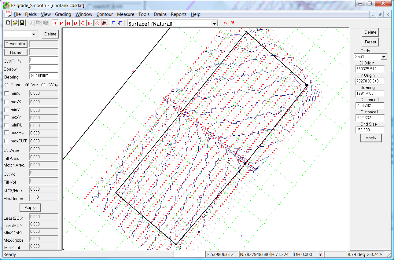
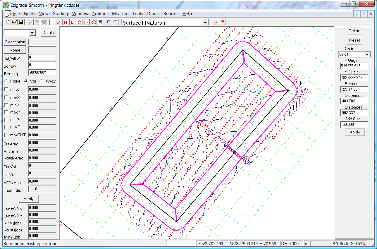
In this design we have designed in a counter clockwise direction. You will notice that the end node finishes before the start node. If you look at the profile you will see the square nodes. These can be considered as grip points. If you click on one of these it changes color to a cyan. You can then left click again and while keeping the left button pressed you can move the node. If you move a node the drain/bank is recalculated. Alternatively you can click on the Drain - Recalculate. At this stage we haven't specified a profile or how the sections are to be displayed. We will simply have the position of the sections. We have the following:
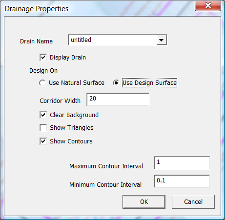
If you click on the "Drains - Properties" menu item you can set some options for this drain/bank. In this bank we need to specify that we want to use a "Design Surface" and that the corridor width is set at 20. The corridor width needs to be wider than the maximum expected width of the designed bank. However this value can be changed on the fly if we need to modify it. Everything is recalculated accordingly.
 Designing the height of the dam.
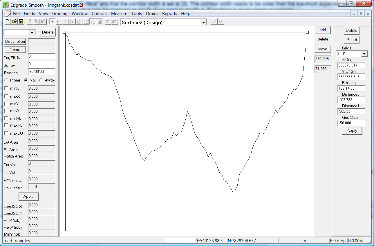
Click on the "Drains - Design Profile" option. We are presented with the natural surface. We can then click in the new design profile. As we are designing a ring tank the height is a constant value. If you look at the screen shot below. You can see the existing natural surface. The design is clicked in at the top; using the Add, Delete and Move buttons. You also can take note of the design height shown when you move the mouse.
 Designing the section of the bank
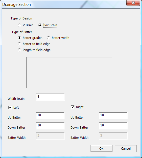
Click on the "Drains - Design Section" and you are presented with the following dialog. In this case we want a flat top on our bank and batter to the appropriate surface. So we have a "Box Drain" type design. The type of batter is just a "batter grade". The width and the batters are entered at the bottom. When happy click OK.
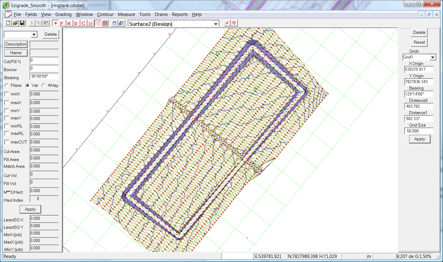
Now click on the "Drains - Recalculate" menu item and view the design:
At present the drain/bank potential design is shown on top of the existing natural surface. At this stage it would be worthwhile checking the volumes in the dam wall. Click on the "Drains - Report Volumes" and it shows that we have a bank volume of 8100 cubic meters. This design is all fill.
We now wish to create a design surface that incorporates this design. Firstly click on the "Tools - Copy Natural Heights to Design" menu item. This sets all the points so that there design height is the same as the natural height. Now click on the "Designs - Merge Drains to Design" and the drain/bank is added to the design surface. Initially you wont see anything as the drain is still shown. Untick the "Show Drains" icon and we will have the following.
If you wished to reduce the amount of dirt needed we could drop the height of the dam wall and make the cut batter smaller if we are dug into the ground. This would balance the cut/fill of the bank wall balance better.
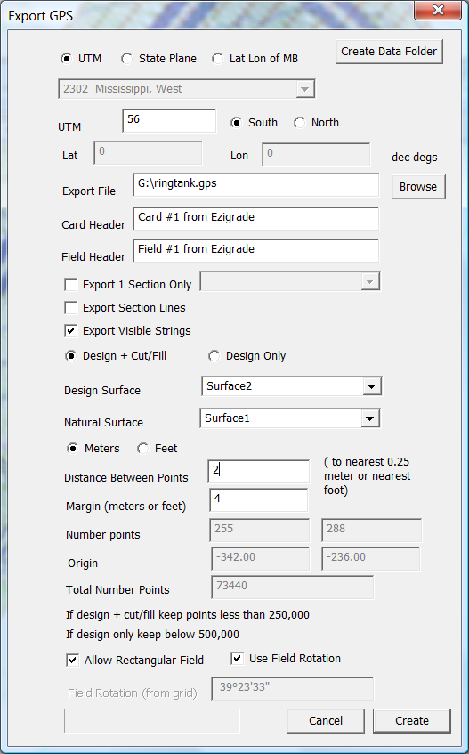
We can now send our design to our respective controller. In this case we will go to Trimble Field Level 2. Fill in the "File - Export Trimble Machine" as below to create a file suitable for the field level 2 controller.
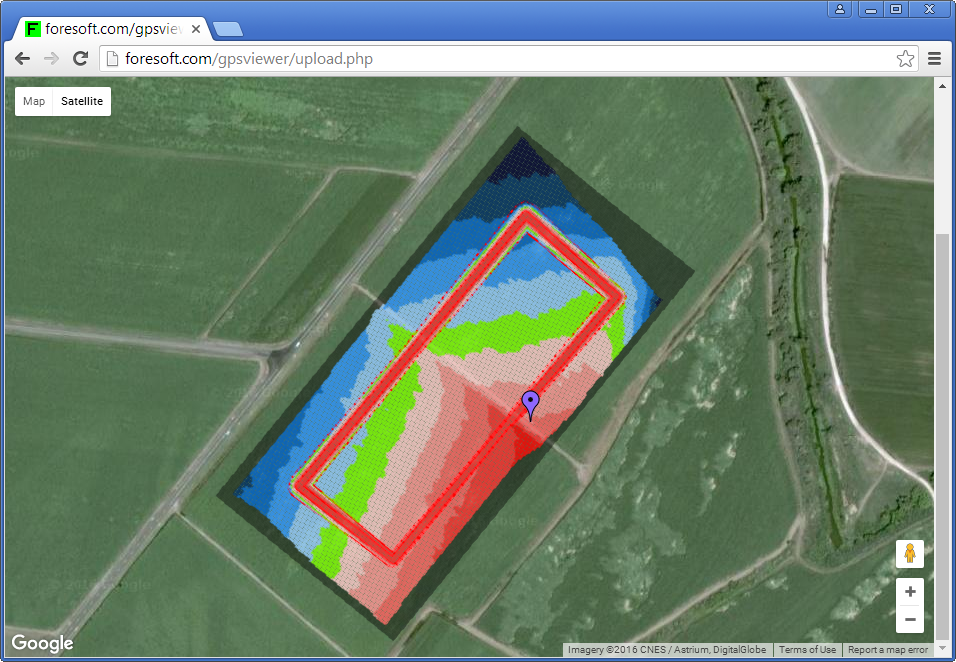
To check before sending to the land contractor use our online file viewer at "http:://www.foresoft.com/gpsviewer/browsefile.php"
The above is simply an introduction that what can be done with our bank/drain designs. The design technique also lends itself to rural or farm roads and lots of other things than can be designed along a corridor.
|