| < Previous page | Next page > |
|
Interpolate Profile's and Section's from a Model
In this tutorial you will learn how to
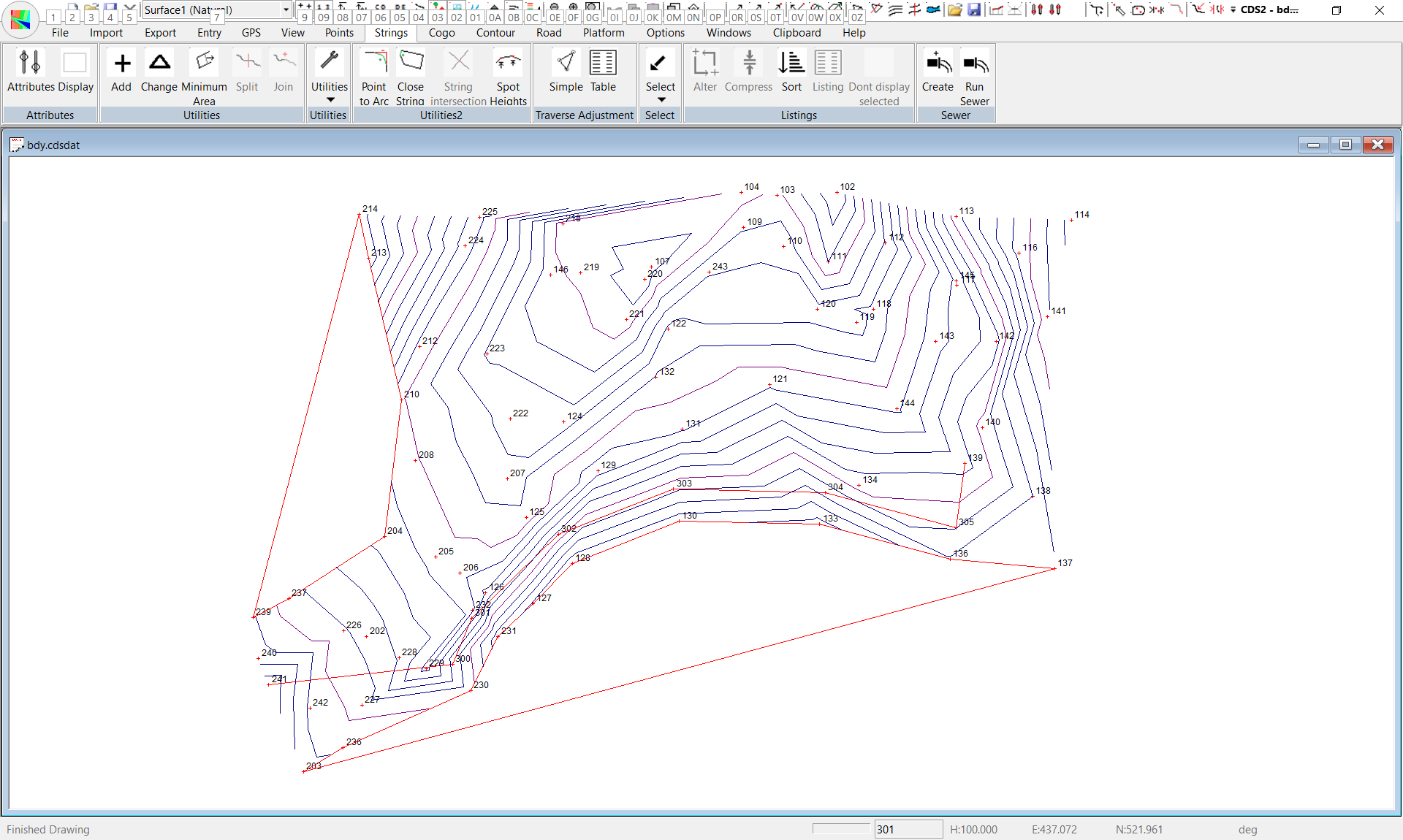
In this tutorial we are going to do some more work on the data we used in the boundary tutorial, so after you start up CDS you should Open Job "BDY" in the Foresoft\cds2\tutor folder, and then Maximise the window showing Job BDY.
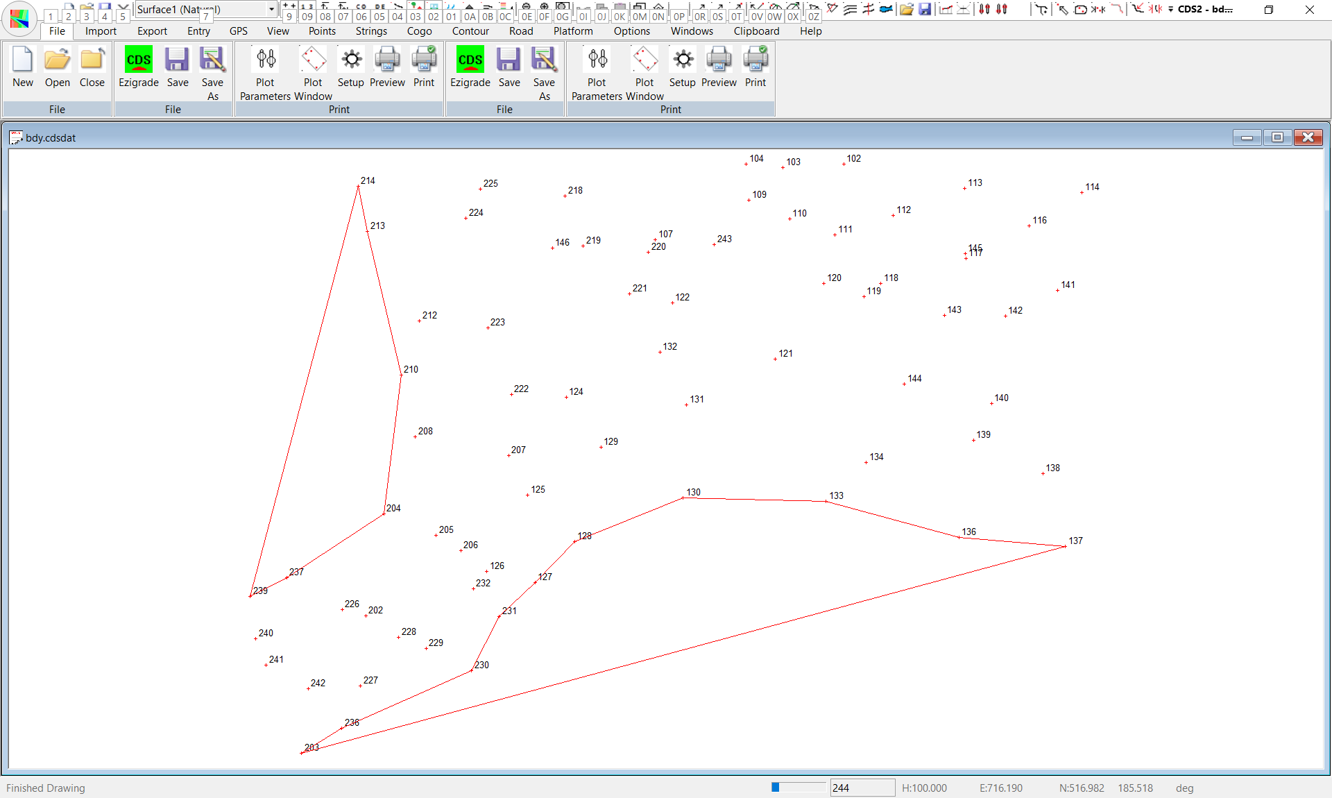
At this stage you should see a screen like the one below.
Since you only need a general picture to start with, you can achieve this easily by interpolating a simple profile.
Simple Profile.
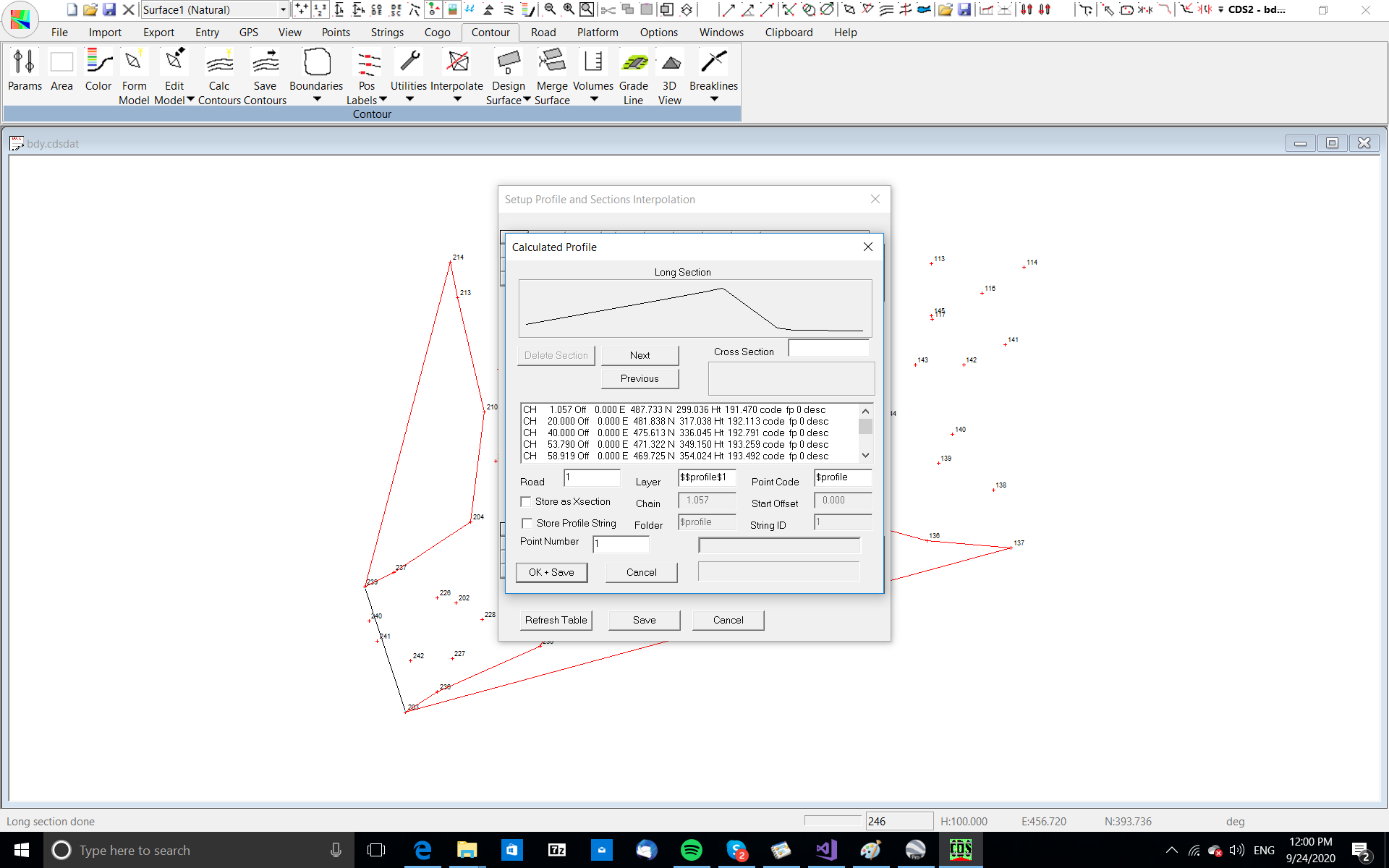
You can see the general lie of the land from the profile shown in the graphic window, and you can also look at the values shown in the window below. Here you see that if you wish to provide the client with an access with the best possible view of traffic on the main road you should start the access at the high point which is around point 241. (And yes I know you might have worked that out from the point heights, but you wouldn't have learnt what a simple profile does if you just did that). If you wish, in your own jobs, you may store away these interpolated points by assigning a Road Number, and a layer and code if applicable, and then pressing the OK+Save button. Here we have no need of saving the information, so press cancel and move on.
Multi Profile.
Now your client has told you that the local fire authority require her to provide a firebreak along the boundaries of her block, and she thinks that she may be able to use her access road as a firebreak. To achieve this she would like to see the feasibility of a road parallel to the southern boundary. As a first look at the possibility of this scenario, you should look at a profile starting near Point 241, running across to the boundary near Point 229, and then following around roughly parallel to the boundary until you get around near the proposed house site near Point 139.
You should pull down the Contour Menu, highlight the Interpolate option and select Multi Profile. You will see the status bar tells you to "Use mouse to click in points for profile, Press Enter to finish". What this means in more common English is that you should “sketch” where you want the profile taken by moving your cursor around the screen and “clicking in” a point wherever you want the profile to change direction. Then, when you have completed your “sketch”, you press the Enter key on the keyboard to indicate to the program that no more points will be supplied. Note that a Multi Profile is made up of straight lines only, and if you need curves to define your profile you should calculate the required alignment points, add them to a string and use the String Profile option.
So, following this cryptic instruction, put your cursor over Point 241 and press the left mouse button.
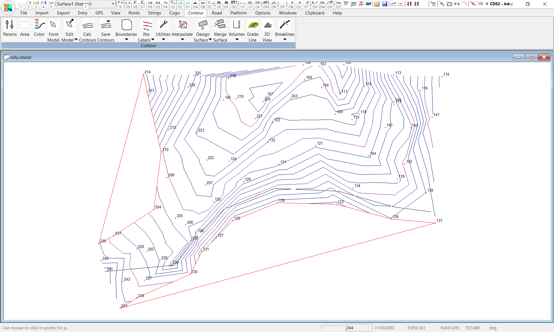
Now move the cursor across to near Point 229 and again press the left button. You will see the line drawn to show where the profile will be taken. Now, you can simply "click in points" to keep the profile line roughly parallel to the boundary as seen in the screen at right. Remember, the principle application of this option is for a quick preliminary profile, so we are not interested in millimetre accuracy at this stage. Once you have 'sketched' the position of the profile and positioned the cursor over Point 139 you should press the Enter key to terminate the multi profile.
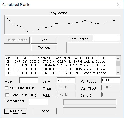
The program will now calculate the interpolated points for you, and display them as seen in the screen at right. If you examine the graphic representation of the profile, you will see that apart from a creek crossing near the main road, there doesn't appear to be any major impediment to taking an access road around this route. While no grades are shown at this stage, you can if you wish scroll down through the values shown in the table, and do quick mental 'sums' from the chainages and heights shown and you will find that there are no particularly large grades to be found.
If you wished, you could store away this profile by assigning it a Road Number and a Start Point ( and possibly a layer and point code ) and then plot it out, however, since it is only a first look we will not save it in this exercise. Now that we have established that there is no major impediment to a road along this southern boundary, we should try and establish a proposed route for the road a little more precisely than simply sketching as we have done. Your client has advised that she would like to have the road "about 20 metres off the fence", so we have determined some bearings and distances for you to use to calculate the position of the centre of the road. We hope that in this location the road will also satisfy the firebreak requirements.Use the Cogo option Bearing and Distance that you learnt how to use in Tutorial 1B to calculate the following points
From Point To Point Bearing Distance
230 300 325 20
231 301 305 20
128 302 335 20
130 303 350 20
133 304 10 20
136 305 10 20
Once your points have all been calculated, you need to create a string to define the preliminary centreline of the road.
Pull down the Strings Menu and select the option titled Add. When the Add Strings Dialogue box appears, type in a folder name of 'road' and a string ID of 'cl'
You can either point to the points with the cursor, or type in a string definition which will be 241, 300.305,139.
String Profile
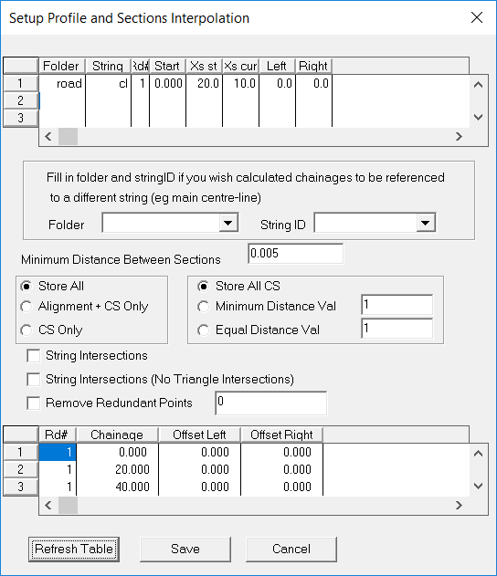
You need to select the string or strings you wish to use to interpolate a profile. In this case we only have one string, so pull down the Strings menu, highlight the Select Strings option and then choose Single String Selection. Position the cursor over the string you have created, and select it. Once the string has been selected, pull down the Contour menu and highlight the Interpolate option, and this time select the option tilted String Profile. You will see that a default Road Number of 1 has been set and that is OK. At this point in time, select the button at the bottom of the screen titled ‘Refresh Table’, and you will see the table now appears as seen below. This indicates that you will interpolate a level at even 20 metre intervals, as well as at the points you have included in the string.
Since we are vaguely satisfied with this location, we will go on and take some sections to go with the profile, and store them all at the one time.
Profiles and Sections.
You will need to select the centreline string once more before you proceed with interpolation of the profiles and sections.
Once the string is selected, pull down the Contour menu, highlight Interpolate, and select Profiles and Sections.
You will find a screen appears which is remarkably similar to the one you saw when you selected String Profile.
In fact, it is exactly the same screen, with the principal difference being that the program automatically fills in a default value of 25 for the fields titled Left and Right when you indicate you need sections. (this will give you sections which are 50 metres wide)
Once you select the “Refresh Table” button, you will see that the screen appears as seen below. Note that if you wish to have different width sections interpolated, you can simply change the values for Left and Right.
To get started, pull down Road -> Display & Plotting -> Display Profile. You will see the profile drawn. Now pull down Road -> Display & Plotting -> Display Section. You will see the first cross section drawn in a new window.
Now pull down the Window menu and select Tile Roadworks to obtain a screen like that below.
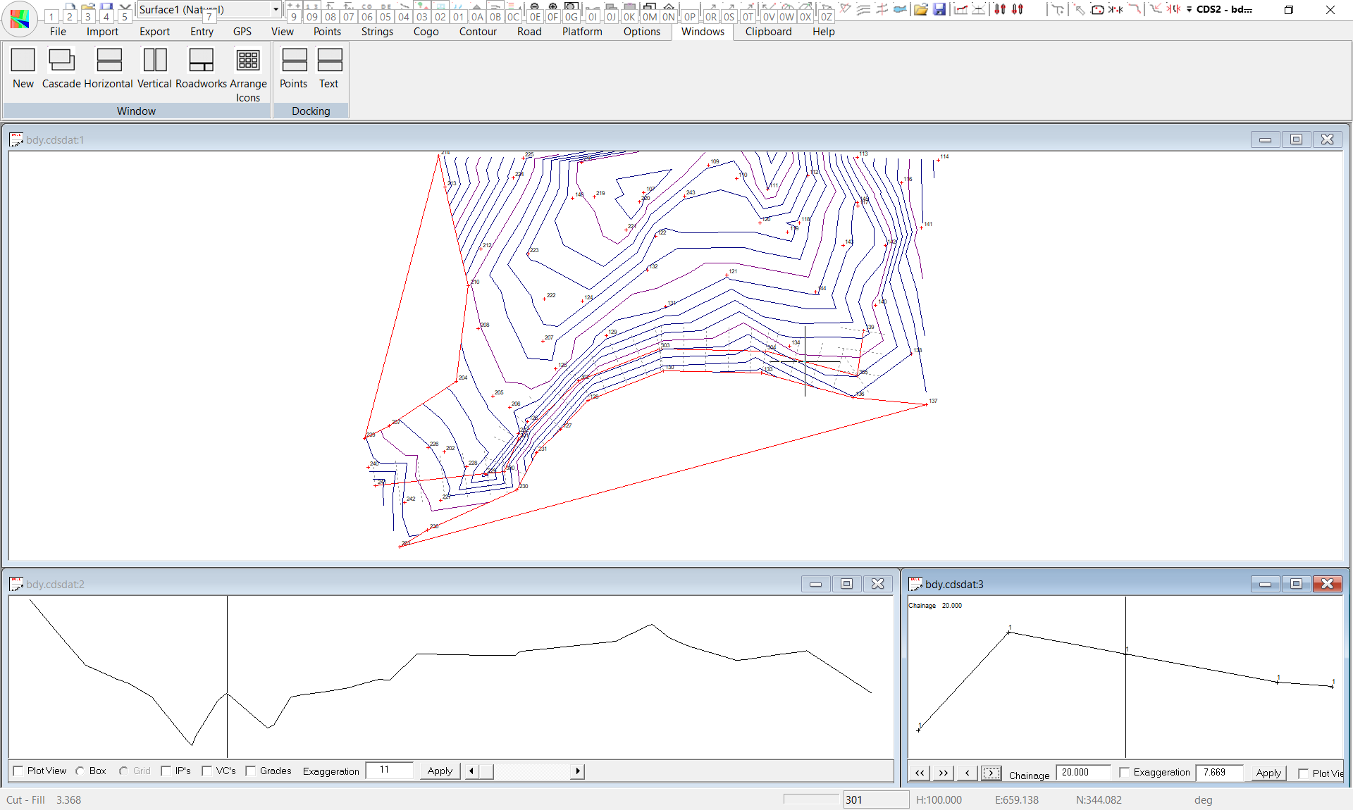
Here you see the plan view of the job showing sections in plan view, together with your Profile and Section.
Refer to Tutorial 5 to reinforce how you apply the techniques you learnt there and how to achieve a plot of both profile and sections.
|