| < Previous page | Next page > |
|
Receiving Data for Construction Set Out.
Introduction.
It is becoming more common for Construction Contractors to be offered data in 'digital format' to prepare tenders and to arrange to set out the project for construction.
While this 'digital data' has the potential to save the contractor large amounts of time, unless it is supplied in a 'useful format', any attempt to use it will result in an enormous amount of frustration and waste of time and money by the contractor.
Before we commence, it is essential for all parties to understand that the preparation of all construction drawings, whether manually or by CAD, involves an inherent and largely unavoidable conflict between the aims of the designer/drafter and the needs of the contractor in the field.
The designer/drafter attempts to create a drawing which best displays their creative/artistic design and drafting ability. As a result of this understandable desire, the drawing is 'embellished' with text, symbols, legends, title blocks and the like.
The contractor needs a drawing that shows the accurate position of the elements that need to be constructed on the ground. This can usually be achieved by a relatively simple line drawing that shows the lines/arcs that define the constructable elements and a scale and origin, or coordinate grid.
From the contractor's perspective, all embellishments are at best distractions or at worst sources of confusion and error.
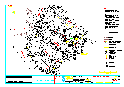
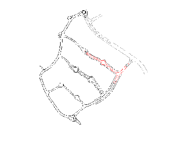
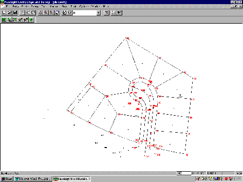
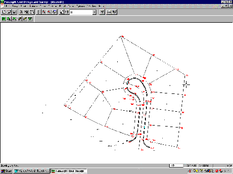
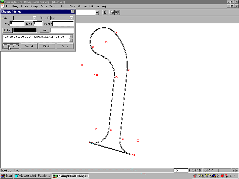
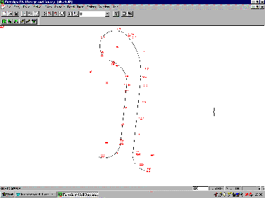
To make this a little clearer, below left is a real life example of a drawing that was provided to a contractor, while the drawing on the right is all that the contractor actually needed to be able to quote and /or construct the job.
It is helpful if all parties understand that there are two broad types of software used in producing Civil Design Drawings, and these are described below.
Survey / Design Software
Packages such as CDS, civilcad, Geocomp, Liscad, MOSS, SDRMap, 4D all concentrate on designing the elements necessary, and mostly calculate the location of those elements.
The 'calculation' process tends to create a more contiguous set of points e.g. you will usually calculate all the required points along one side of the road before doing the same on the other side.
They can output the coordinates of the points defining the elements into a relatively simple file which essentially contains a list of the coordinates which the contractor needs to peg or mark the points on the ground. This file is often called an ASCII (ass-kee) file.
They can also 'upload' these coordinates into data collectors and total stations for use in the field.
These programs usually have the ability to prepare 'stakeout reports' to allow the contractor to easily set out the required elements from pre-defined control points in the field.
Drafting Software
Autocad, Microstation, etc.
Generally a computerised version of the manual drafting process where elements are 'drawn' rather than calculated.
The drawing process tends to create a more discontinuous set of points. Since things are 'drawn' to arrive at a suitable picture, what the order in which things are created doesn't matter .
This drawing process often results in two or more 'points' being created where lines or elements intersect. No method of uploading the required points to a data collector/ total station. No inherent ability to produce a 'stakeout report'. The data is supplied in either a DWG (drawing) or` DXF (drawing exchange) file.
It is also important to understand that often the two types of software are used in combination to arrive at the finished set of plans, particularly since the 'Drafting' packages are generally not capable of producing contours or long and cross section by themselves.
If we take a typical (if simplified) scenario concerning the design of the road for a new subdivision such as the one in the drawings above, the process goes like this;
a. the initial survey is done in the field by a surveyor who will bring the data into one of the Survey/Design programs to produce the base plan with contours.
b. the centrelines of the proposed roads are then overlaid on the natural surface base plan. This can either be done in the Survey/Design program, or the base plan may be converted into a DWG file to allow the proposed layout to be 'drawn' with the Drafting software.
If 'drawing' is used, the design alignments are imported back into the Survey/Design software
c. profiles (and sections) are taken along the proposed roads - this is usually done in one of the Survey /Design packages, (and if it is not then the designer is probably wasting time and money).
d. the roads are then graded, and final road designs are arrived at using either section templates or string profiles, or a combination of both. - again this is usually (or should be if it is not) done in one of the Survey /Design packages.
e. design contours are produced.
f. the design & natural contours are exported to a DWG and
g. the drafter sets about creating a final drawing which is a work of art.
Now, from the point of view of the construction contractor, sufficient information to stake out the job is available at the completion of Item (d), and there is enough information to quote on the earthwork quantities, at the end of either Item (d) or Item (e).
So, considered correctly, anything that is done after Item (d) can only interfere with the smooth flow of the information which the contractor needs to stake out the roads prior to constructions. And, anything done or added after Item (e) can only get in the way of the construction contractor no matter what he wants to use the data for.
Now, in days gone by, when it came time to call tenders, the full (if not final) set of plans produced at the end of Item (g) would be handed over to all prospective tenderers to determined their own quantities.
And, because we humans are creatures of habit, that is still what tends to happen, even though the set of plans is now in the form of a DWG file on a disc or CDROM, or, if you are really dealing in high tech, sent by email.
All very well if the aim of the exercise is to have the tenderers admire the drafter's artistic ability.
BUT, if the aim of the exercise is to allow the tenderers to efficiently prepare a quote, then unfortunately this attempt to digitally follow the manual method is only creating confusion.
If we lived in an ideal world, the contractor would have a 'computer whiz' available to manipulate the data to screen out the stuff that is not needed. But we don't live in an ideal world, so construction contractors generally are not overrun with computer whizzes, and even if they were, it would still need the drafter to provide a meaningful list of the Layer names used in the drawing to help the filtering out process.
What to Ask For.
So, how does the construction contractor go about getting the data needed in a 'useful format'.
Quite simply, approach the firm providing the tender drawings with a smile, speak softly and carry an expensive bottle of scotch. And no, it is certainly not a bribe, that sort of thing doesn't happen in the construction industry, it is simply a fee paid in kind for services rendered.
The following steps are in order of decreasing preference from the point of view of trying to get the data into a Survey/Design package to produce a stakeout report and/or upload coordinates to a data recorder.
1. Obviously if the firm providing the tender drawings is using the same Survey/Design software that you have, ask them for a copy of the Job they used up until Item (e) in the scenario above, as well as the tender drawings.
2. If they are using a different Survey/Design package you will need to ask if they can provide the data in an ASCII file with only the coordinated points of the key elements. i.e. can they give you the data from the Survey /Design software at the end of Item (d) above.
For example, you can ask for the following files depending on the package the firm is using.
If they are using MOSS, ask for a GENIO file - all other serious Survey/Design packages can read it
If they are using civilcad, ask for a GENIO file or a civilcad ASCII file.
If they are using Geocomp ask for the Points & String files from the JOB, or a MOSS GENIO file.
Note that these files are required in addition to the 'Tender Drawings", because typically some key information will be included by way of comments on the final drawings rather than in the data.
3. If they have produced the tender drawings exclusively with a Drafting package, ask if they can provide you with another drawing which only has the elements to be constructed in it.
The Drafter who produced the tender drawings should be able to achieve this in a couple of minutes so it is no huge imposition to ask.
To achieve this outcome using Autocad, the drafter would turn off all the layers except those containing the elements of interest. Next use the "WBLOCK" command to write a block, and select the objects by placing a window around all the objects which are currently displayed.
You then import this drawing into your Survey/Design software.
4. If they don't wish to proceed with item 3, ask if you could have a copy of the tender drawing in which all layers except those containing the elements to be constructed (in this case the roads) are turned off.
You then import this copy of the drawing into your Survey/Design software so you only get the points that you are interested in and not all the embellishments.
The difference here between Items 3 and 4 is that the drawing produced in Item 4 will be significantly larger than the one in Item 3, and so will take significantly longer to read in and process in your Survey/Design software.
5. If they are unable or unwilling to provide a separate drawing with the layers turned off, then ask them for a list of the Layers they have used in the drawing, and what is intended to be on each of the layers.
At least then you have somewhere to start when it comes to filtering out the surplus information.
Note: If you think you will be dealing with this scenario on a regular basis, I would strongly advise you to obtain either Autocad LT or Intellicad, or Turbocad, so you can use these "Drafting" packages to display the drawing you have been given and turn off the layers you don't need before you use the WBLOCK or similar command to produce the drawing referred to in item 3 above.
While construction contractors have an understandable reluctance to get involved with Drafting packages, in these circumstances it is a tool which can save you enormous amounts of time and money, so please think about it.
6. If they are unable to provide a list of layers then experience has shown they probably don't have much of a clue about what is going on, and the digital data is likely to be in a complete mess anyhow, even if the drawing does present a 'pretty picture".
In these circumstances, which are regrettably common, a paper plan if probably safer, and certainly less frustrating because you are not likely to become infuriated by what could have been.
How to Deal With What You Get. - A Practical Example
OK, lets assume the worst happens, and you are dealing with a Type 5 Firm who can at best manage to give you a drawing and a list of the layers they used in the drawing.
You don't have any Drafting type software and you need to get some information out of the drawing to prepare a tender submission for the construction of the kerb and gutter and paving for a new road in a small subdivision.
The file you have been given is called Civil1.dwg and you have it stored on your computer. (The more perceptive of you might notice a striking similarity of shape between this drawing and one called 'lotdwg' elsewhere in the tutorials - when you are on a good thing stick to it.)
Start CDS and open a new job with a name of civil1.
Note that it is possible to import a drawing into an existing job, however, until you become very skilled at playing with drawings, I strongly suggest that you bring each drawing into a new job, fool around in that job to get the data you want, and then transfer the useful data to the existing job.
If you choose to import directly into an existing job so be it, but please make sure you have a backup of the job before you start. If you don't, and you screw up your data, don't call us because no matter how developed our acting skills are, it is very difficult to feign sympathy in the face of negligent stupidity.
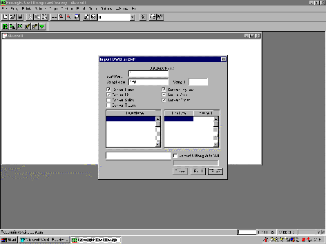
The first step is to Read the drawing so the program can determine what is contained in it, so select the Read button.
The screen should now appear as below.
Please note that at this stage of development you cannot turn the layers off or on in this screen - it may come later, but for the moment you can see but not touch the layers in the drawing.
In this instance, we have started a new job, so the point numbers can start from 1, but if you choose to import into an existing job please set the point number to a number above your existing points.
Select the Save button and the drawing will be read in to the job.
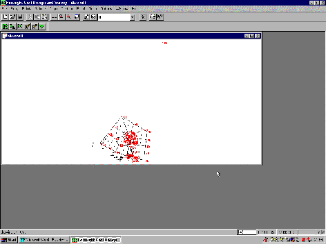
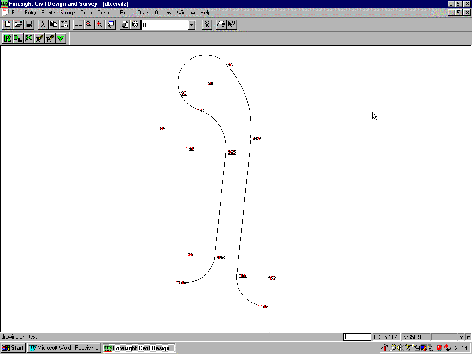
When the blank CDS screen resumes, press Z followed by E to zoom to the extents of the job, and you should see a screen like that below.
Note that there is something recognisable at the bottom of the screen, and another 'blob' of points at the top of the screen.
Since we are interested in the kerb, you should select all the strings that make up the kerb.
Pull down Strings, followed by Select, and Select Individual Strings.
Point to each of the stings in turn until the entire kerb line is selected.
Note that in the case of an arc, if you zoom in close and point near one of the tangent points, about on the line of the chord you will identify the curved string
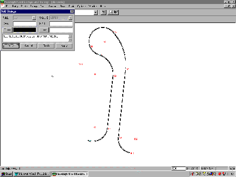
Once the entire kerb is selected, as seen in the screen below, pull down the Point menu, then Select, and choose Select Points by Selected Strings.
When presented with the window asking what folder to paste the strings into, I suggest you just select OK to let the program do as it chooses.
Then Zoom Extents to see a job like that below.
Now, before you start to relax, the job is not over yet, and you still have some more data housekeeping to carry out.
First of all, if you clear the selected points (either press Esc, of pull down Points, Select, Clear Selection)and then look closely at the screen, you will see some points overwritten at the ends of the straight section of road.
This is relatively common with data which comes from a drafting package, particularly when the designer has 'drawn' each of the elements (ie the lines and the arcs) separately, and not bothered to make them all into a continuous polyline.
Remove Duplicate Coordinates
Pull down the Options Menu, select QA Routines, and then select Filter Duplicate Coordinates.
The Coordinate Tolerance of 1 millimetre will be fine.
You will see the box titled Keep Points used in Strings is selected. This might be sensible for some data, but generally speaking when data comes from a 'drafting package' all the points are in strings, so if you leave this selected nothing will be done. I suggest you clear the tick.
You will also see a radio button titled User Selection is highlighted. Again, in the case of data from a drafting package this is not ideal, and if you leave it selected the program will drive you mad asking you to decide which point it should keep.
Instead, select the button titled Delete Higher Numbered one.
Select OK, and when the screen returns Press D to reDraw the screen. The duplicate points should now have disappeared.
Form a Continuous String.
Now if you look at the picture, it might seem that the kerb line is drawn just fine, and you could extract the information you need.
Problem is, while the picture is OK, the lines which make up the picture are not arranged in a continuous sequence, so it is difficult to arrive at a total length.
Also, they do not form an 'closed' string so it is not possible to calculate the area enclosed.
It is possible in some circumstances to select adjacent strings and then use String, Join to join them together to form a continuous string. However, this particular arrangement of strings does not lend itself to the process because of the way they have come from the drawing.
Here it will be far quicker to simply Add in a new string which is continuous from start to finish.
Pull down Strings, select Add, use a string name of Kerb, and enter the following string of points;
100,-99,98,89,-90,91,+92,95,+96,97,101,-102,103
As you can see, the 'picture' of what you have just defined looks exactly the same as the picture you had before, but now we have one continuous string (or polyline if you like) which is in a form that is 'useful'
Calculate Length of Kerb Required.
Now pull down Strings, select List, choose a full listing, and you should see the following report appear in Wordpad.
JOB NAME: C:\My Documents\Nututs\civil2
Date: 18/08/1999
_________________________________________________________________________
Folder: lots String ID: kerb
PERIMETER 196.129 m
OK, you now know you need to price 197 metres of kerbing.
Calculate Area of Pavement
Before you can calculate an area, you must have a 'closed string' enclosing the area required.
Here, if you close across the 'neck' of the road you can achieve what you need.
Pull down Strings followed by Change.
Select 'Kerb' from the pull down list, and you will be presented with the string of point numbers.
Place the cursor to the left of point 100, and type in '103,'.
Now select Show, and the screen will appear as below.
Select Finish.
Now Select the Kerb String again, and then use Strings, Listings to obtain the following report in Wordpad.
JOB NAME: C:\My Documents\Nututs\civil2
Date: 18/08/1999
Folder: lots String ID: kerb
PERIMETER 225.355 m
AREA 933.979 sq.m
You now know you have to quote on 934square metres of pavement material.
Due to the fact that you got the quote in faster than you have ever done before, you have now been awarded the contract.
Setting out the Kerb.
It is customary to peg the kerb at an offset, and here we wish to place pegs every 10 metres at a distance of 1.5 metres behind the line of the kerb.
Before we proceed, we need to take out the 'closing line' we just put into the kerb string to calculate the area.
Select Strings, Change, pick kerb from the pull down list, and take out the '103,' at the start of the line. Select Show followed by Finish, and you will be back to a string that just shows your kerb line.
Now pull down the Cogo menu and select Road Calcs followed by Autoroad.
Pull down the folder list and select 'lots'
The pull down the String list and select 'kerb'
Check the button titled Alignment plus Chainage to calculate an offset point at each of your TP's plus every 10 metres.
You already know that this kerb is 197 metres long, and you want a peg every 10 metres, so fill in the table with zero in the From column, 200 in the To column and 10 in the Interval column.
(if you want to get real fancy, you could have different intervals for different chainage ranges e.g. peg every 1 metre around your curves, and every 10 metres up the straights - it is just a matter of filling in the table).
For ease of later manipulation it is a good idea to commence new 'batches' or points you calculate at an even 10 or 50 or 100, so here enter a new point number of 200.
In the Offset Table enter a value of -1.5 to indicate you want to offset to the left of the string (facing in the direction which the string is defined).
You may 'play' with the other boxes as the mood dictates.
Once you press OK the points will be calculated and appear as below.
CDS + CDS_Premium Receiving Data for Construction Set Out Page - 9
|