| < Previous page | Next page > |
|
Dam Wall Tutorial
In this exercise you will
Start CDS, and use File, Open, to access Job “DAM” which will be in the tutor folder, and Maximise it.
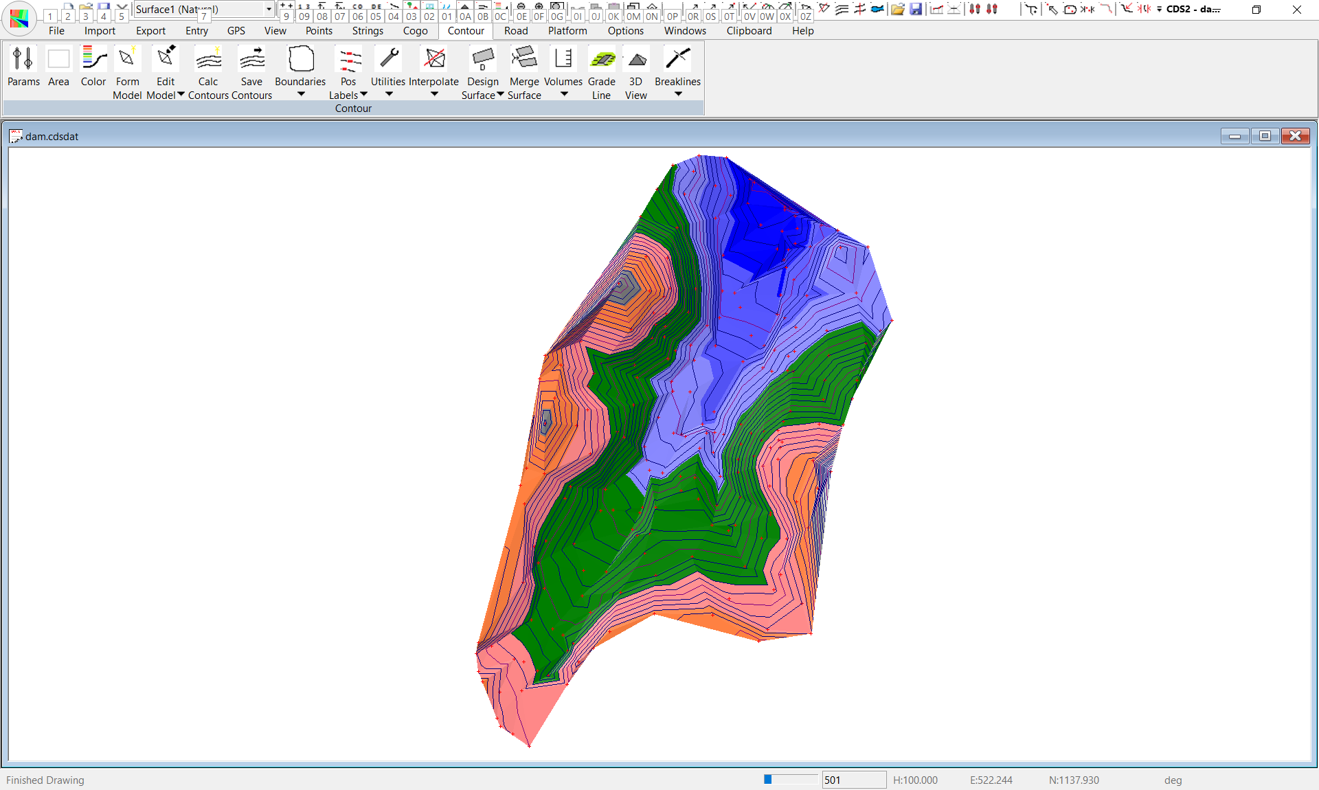
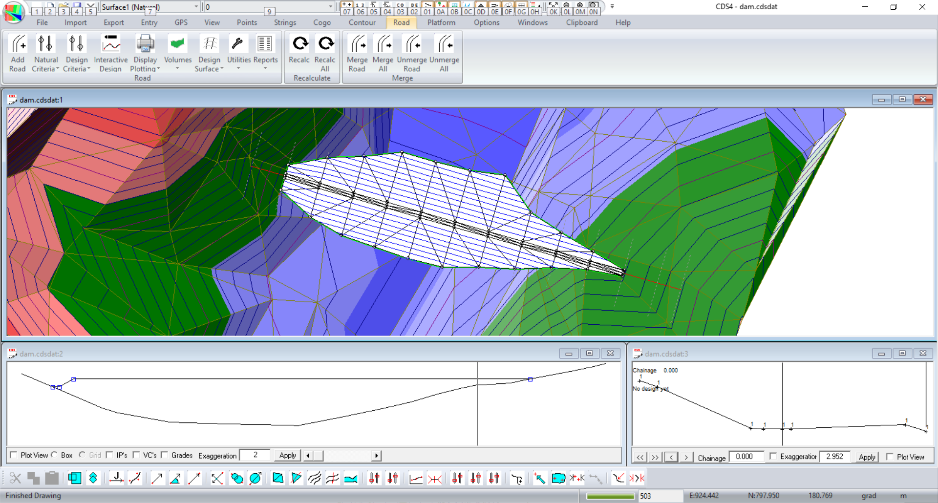
Now Pull down Contour, and Form the Model and then Calculate Contours and Save them to see a screen as shown below.
Some preliminary investigation has been done. The design coordinates of the end points of the proposed wall have been decided on, and are listed below.
West End: E- 739 N- 862
East End: E- 983 N- 792
Our first task will be to add these points to the job.
Pull down the Points Menu and select Add Points to change the cursor to a cross.
Now position your cursor somewhere within the surface and press the left mouse button.
The Add/Edit/Query screen will appear and you need to decide what Point Number to add in.
It is a good practice to start new ranges of points on even hundred or thousand values, and in this case we will assign points for the wall from Point 600.
Enter in Point 600 and then the relevant coordinates for the west end point.
Now repeat the process to add Point 601 on the East end of the wall.
Now pull down the Points Menu again, and turn Off the add points option by again selecting it. (or press the Escape key to turn it off)
Once both points are in, we need to create a String showing the centreline of the proposed wall.
Pull down the Strings Menu and select Add.
Now drag your dialogue box over to the right hand side of the screen so it is clear of the data.
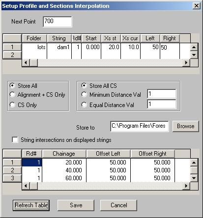
The default Folder of ‘lots’ will be adequate, so enter an ID of ‘dam1’.
Don’t worry about Pen or Linetype at this stage, and simply add in the string 600,601 for the proposed centreline.
Extracting Natural Profiles and Sections
Cross Sections at 20 metre intervals are sufficient for this exercise, but you should be aware that the Xs on St and Xs on Crv fields allow you to specify whatever section intervals you like, and you can have different intervals in straight and curved sections of the alignment.
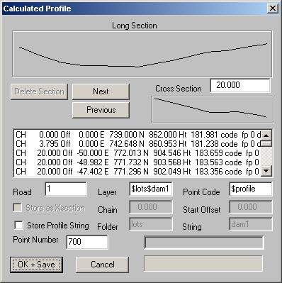
In the smaller middle window, you can see the first cross section, and if you wish, you can use the Next and Previous buttons to move backwards and forwards through the cross sections.
Providing you screen is vaguely similar to the one shown above, select the OK+Save button.
You will see the bar in the bottom right corner scan back and forward to alert you to the fact that things are progressing, and once the points are stored, you will be returned to the previous screen.
Since we have no further need of it at this time, select the Cancel button.
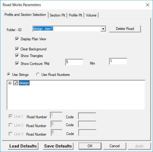
CDS goes ahead and creates a new Road and displays the outline on the plan view. You can turn this display in the plan view on and off by clicking on the View -> Roads icon.
We now wish to view profiles and sections. In the icon's along the bottom you can see icon's 22 and 23 from the left. Click on these two icons. Arrange the Views by clicking on Windows -> Roadworks. We get the following:
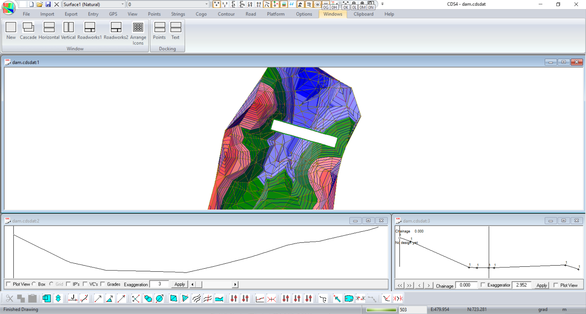
If you wish to see the sections, you can use the Next and Previous buttons, or the scroll bar to move through them.
The first thing we need to do however is to enter the Vertical Design of where we would like the dam wall to be. We wish to construct a dam wall with a height of 181 and allow 1.5 metres freeboard.
Enter the Design Grading
To achieve this it has been decided to construct a small spillway at RL 179.5 at the western end of the wall.
Since we are going to work on the profile design, Maximise your profile window, and then click your Right mouse button to see the design options available.
The first thing we need to do is to Add a point to start from, so select the Add option.
Then move your cursor around on the profile screen, and you will see the Chainage and RL being tracked in the windows on the status bar.
We need to put in a point which is somewhere near the left hand edge of the window, so move the cursor over there and watch as the height approaches 179.5.
If you are steady enough with the mouse you can press the left mouse button to add in a point with an RL of 179.5. If not, use the right button to bring up the options, select Design IP Table.
In this case the Chainage is not critical as long as it is around zero, but we need to type in the exact RL of 179.5 and then select the Save button.
You will see a small box signifying a Vertical IP that appears on the profile.
Again press the Right mouse button to bring up the available options.
What we are attempting to do is to locate where RL 179.5 is on the existing profile, and we will use the “dummy” IP we have already entered to establish that point.
Choose the option Add Grade to Natural, and when the program prompts for the IP, select the IP you previously added.
A window will pop up requesting the grade to use, and since we wish to be level from the first IP use a Grade of 0 and press OK.
You will now see another IP appear on the profile, and this will be at RL 179.5.
Next we wish to define the spillway, which is 3 metres wide and level, so use the Right mouse button to bring up the options, and select Add by Grade. Use a Grade of 0 for a Distance of 3 metres and select OK.
Again use the Right mouse button and choose the Add by Grade option, and selectg the IP to grade from.
This time we wish to batter up from the spillway to the top of the Dam Wall at a batter of 1:4, or 25%. Since we need to go up 1.5 metres at 1:4, basic arithmetic tells us we need to go horizontally for 6 metres.
So, enter your Grade of 25 and a distance of 6 and select OK to see another IP appear at what will be the top of our wall.
Back to the Right Button and choose Add Grade to Natural.
Select the IP to grade from and use a grade of 0 and select OK, and you will see another IP appear on the profile at the right hand end.
All that remains is to dispense with the “dummy IP” we used to get started, so bring up the options with the Right Button, choose Delete, and point to the first IP.
Now that the Profile Grading or design is completed, select the Tile icon to again tile the profile and section windows, and we will set about designing a template to use to construct the wall.
Create a Design ‘Template’
In CDS terminology, a “template” is simply the right hand side of what you would like the design cross section to be. If you are building a symmetrical structure, you can then mirror that template on the left hand side, or you can use a completely different one if you wish.
There are a number of predefined templates available which saves you the time of specifying the template yourself. For simple examples like this you may be able to get away with this method. For more involved designs you will need to define it completely as mentioned further below.
Creating the template using predefined examples.
Creating the Template by filling in the table:
Often for more complicated example we need to define our template from the start. As a reference the following procedure would be used to fill in the table by hand. If you are interested please read the following. Otherwise you can ignore the italic text below:
This table allows you to construct the template using a wide variety of options, and you access the options on each line by pulling down the list in the “Type” column.
The first thing we need to do is to tell the program where to start building this wall, so on line 1 select the Start option.
You now can fill in the X and Y columns with coordinate values based on a local origin. The origin of these coordinates is where the Vertical Grading intersects with the chainage.
In this case we have designed the grading, and there is no subgrade material to be considered, so we will start the template at 0,0. Ignore the column titled “Tab#” and put in pen and line values of 1.
Now, on Line 2 pull down the options list and choose “Hdist & Grade” to indicate we will specify a horizontal distance and a grade.
The dam wall is to be 3 metres wide on the top, and remembering that our template is the right hand half, you will enter a distance of 1.5.
While it may or may not be good practice, a flat top is adequate, so use a grade of 0. Again skip Tab# and press enter or tab to accept pen and line 1.
We now need to check whether this point is above or below the natural surface, and have the program react accordingly. Since it is a dam wall, this point will almost always be above the natural surface, however we need to consider the case at the start and end of the wall where we may need to excavate a small amount of material.
Pull down the options and choose a Cut condition. Enter values of 0 and 99 to signify any amount of cut, and use condition number 1.
As the program checks through the template, it will consider if the point is in cut, and if it is it will go off looking to find where you have specified Condition Number 1. If the point is not in cut, the program will look at the next line in the template to see what to do.
Logically, if the point is not in cut, it is in fill, and if it is, we wish to batter back to the natural surface with a slope of 1:3
Pull down the options list and select Fill batter at Grade.
Enter a distance of 100 and 1:3 for the grade - it will be converted to 33.333(%), and again accept the default pen and line. This indicates that the batter should go at 1:3 until it reaches the natural surface, or until it gets to an offset of 100 metres, whichever is first.
Now it is time to start on condition number 1, and you should be on line 5.
Pull down the options and select Start Condition. Enter a number of 1.
If condition 1 is satisfied, it means that the point 1.5 metres from the centreline is actually below the natural surface, and if this is the case what we need to do is to immediately batter back to the surface.
Pull down the options and select Cut Batter at Grade. Enter a distance of 100 and a grade of 1:2.
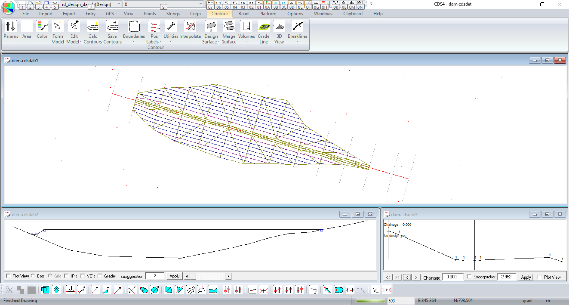
At this stage you should have the screen shown on the previous page.
Once your template has finished, select the Save Option and it will be saved away as template number 1.
Now Click the OK button. The template is automatically saved and the program is informed to use this template at each cross-section.
Next you need to tell the program where to use the template.
Pull down the Road Menu, select Design Criteria, and choose Template Positioning.
You will see a screen with two columns titled 1L and 1R. These stand for Left and Right of Design Line 1. Type 1; in both columns on the first line.
Then, highlight the 1 in the left column with the mouse, and press the Right Mouse button to copy template 1 to all other sections. Repeat the process in the 1R column, and save. CDS also has a dialog box which you may fill in accordingly.
We should now have the following:
The plan view display can be controlled from the View -> Roads icon and also by clicking on Road -> Natural Parameters and clicking on "Profile Parameters".
Having successfully designed the dam wall, we now need to know how much material it will take to build it.
Calculate Volume Of Dam Wall
Pull down the Road menu, and select Volume.
Ordinarily, with other jobs you might need to use the Design Volume parameters Options to set up ranges of chainages to calculate between and what road number to use etc.
However here we are using Road 1 and our chainages are greater then 0 and less than 1000, so everything falls within the defaults and there is no need to make any changes.
If you wish to look, you may do so, but there is no need to.
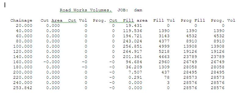
Instead, choose Design Volumes, and you will shortly see Wordpad appear on your screen with a jumble of figures.
Now your screen should appear as at right, and if you use the scroll bars to move to the end of the right hand column you will find that you should need some 28,500 cubic metres of material to build the wall.
If you wish to print this out you may do so with the File print option in the Wordpad window, and if you wish to save it, just agree with WordPad as regards saving in a different format.
Create design Surface
Now that we have a wall designed, we want to create a digital terrain model. Click on Road -> Merge and a new surface is created showing the design.
This is enough detail to create the dam wall and we can export the data to the appropriate grading software in either Ezigrade or CDS.
We now need to construct a ‘combined surface’ so that we can calculate a dam volume.
Forming Combined Surface
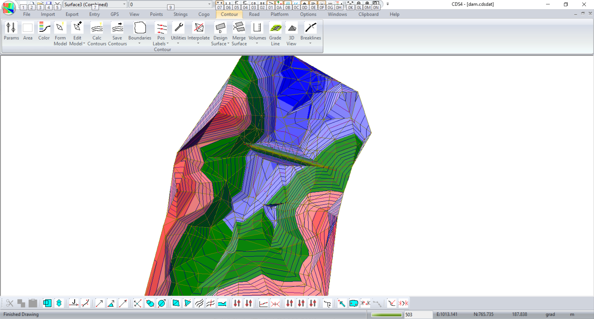
Pull down the Contour Menu, select Surface parameters, and select the Add button to add Surface 3.
Allocate it as a Combined Surface.
Now pull down Contour, select Merge Surfaces, and accept the default surfaces on offer.
Hit the OK button.
Now Form the Model and calculate and Save the Contours to achieve contours as seen below:
Calculate Storage Capacity Of The Dam
Once the Combined Surface is satisfactorily saved, you can use it to calculate the amount of storage capacity in the reservoir or dam you have constructed.
Pull down Contour, select Volume, and choose the Storage Capacity option.
For a Start Point add in the value of East 800 and North 750. In this example there is another area that also has closed contours; and CDS uses this value to decide which closed area to use.
Move down to the Water Level field, and enter a value of 179.5.
In the Interval field enter 0.5
The following screen will soon appear, with the results presented in the now familiar Wordpad, and if you scroll down to the end of the file you will see the screen shown below.
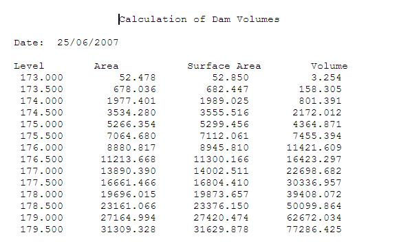
It is important that the combined surface has been contoured before running this routine. The internal program algorithm checks on closed contours to decide whether the water; is in fact contained in the dam or simply running off the page or sheet.
Thus if there is a break in the triangles for example the program decides that the water will escape through this hole and the volume calculation will stop at this level.
|