| < Previous page | Next page > |
|
Traverse Reductions
In this Tutorial you will learn how to
CDS contains a traverse spreadsheet that enables you to define and correct both closed and open traverses. These tables are somewhat rigorous in how things need to be defined.
You can also perform an adjustment on a CDS string that is either an open or closed traverse. You also have the option of using the string and having CDS fill in the traverse table for you.
Traverse table from a string
In the example below we have used the COGO routines, "Bearing and Distance" to add in some points that that should form a closed traverse. As CDS does not allow duplicate point numbers the end point is calculated in with a point number of 5.
Next step is to string the points together. CDS is then in a position to recognize the traverse. From the String menu, select the "String Add" option. Fill in folder and string ID with a recognizable name. The string definition can be added in as 1,2,3,4,5 or in shorthand as 1.5
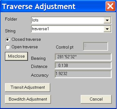
Clicking on the "Transit" or "Bowditch" adjustment button performs the appropriate adjustment. There is no report produced.
Alternatively we have the string option which is more rigorous and recommended. First select the string. ie from string menu and then string select. Now select the start point. ie from point menu and then point select. Now from the string menu and then "Traverse Adjustment" and then "Traverse Adjustment (Table)". The traverse spreadsheet is filled in and all you need to do is select the adjustment procedure that you require. Read the "Entering the Traverse Adjustment with Observed Bearings" for more detail.
Doing Traverse Adjust by Traverse Network Spreadsheet
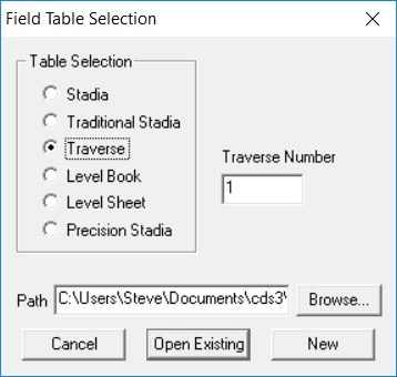
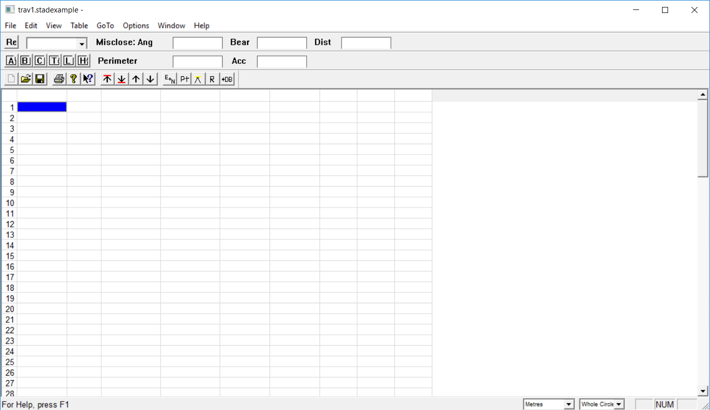
Open a new CDS job and call it stringtraverse. Enter in the start point / station point of 1. We have used coordinates of 1000.0,1000.0 with a height of 10.0. We have used the Cogo funtion, calculate will s a temFrom Windows, select the Start button, and then select Programs to see the list of available programs Pull down the File menu and select New. Enter a Filename of trv, and a Description of Traverse Tutorial, then select Open, and a blank screen will appear. Access the Traverse Entry Screen Use your mouse to select Entry from the options on the menu, and then select Traverse Network.
The screen will appear similar to that below left. Since this is a new job, select the New option, and then maximise the screen so it appears as above right At this stage you need to be aware that traverses are broken into two main groups, defined by how the horizontal angular measurement has been observed and recorded. The two are "horizontal bearings" and "horizontal angles".
If you use bearings in the field, please follow through the next section. The angular section is further on.
Entering the Traverse with Observed Bearings
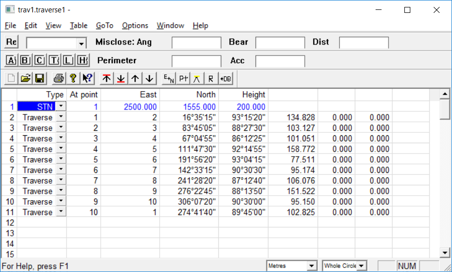
If you are in the habit of observing bearings in the field, then all you need do to get your traverse into the entry screen is to provide a STN record defining the coordinates (either real or adopted) of the first point in the traverse, and then enter the details of the individual legs. In this exercise, the field party has carried out a closed traverse around a parcel of land, starting from Point 1 which has local coordinates of East 2500 North 1555, and R.L of 200.00. From this point a known azimuth could be set to a nearby Trig Station, so true bearings were recorded. In this case the field crew were using older style equipment which required the vertical angle to be read and noted along with the slope distance, rather than the new fangled gadgets which automatically reduce the horizontal distance for you. The following data has been tabulated from a field book
From Station 1 - Adopted Local Coordinates:
East 2500 North 1555 RL 200
The last shot is taken back to the initial stn and is obviously a closed traverse. Alternatively the last shot could have been shot to any new arbitrary point; example 11. The software checks that the start and the last point are close together and is smart enough to treat it as a closed traverse.
Defining the Known Coordinates
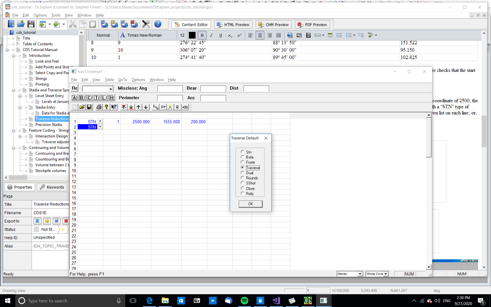
You will see that the default Type of data on the first line is STN, which is exactly what we require, so press the Enter key to accept it. Enter 1 for Stn number, and then the East coordinate of 2500, the North coordinate of 1555 and a height of 200. Now press the Enter key until you finish off the line and the cursor moves down to the next line. The next line will also come up with a “STN” type of entry, but we only need the one station in this particular traverse, so we need another type of entry. You can either allocate the individual entry types by selecting from the pull down list on each line, or, in the case where you will have a number of entries of the same type you can set a default entry type.
Entering the Traverse Legs
Obviously in your real life work, you will need to enter in the values that you measure for both height of instrument and height of target if you are to obtain correct values for the heights of the stations. Enter 1 for both height values, and press Enter to skip over the Point Code column, and you will see the cursor appears on the next line offering a default type of Traverse. Press Enter to accept it, and then continue to enter the data shown in the table until you reach the end, by which time you should have a screen as below:
Define the Traverse Loop
Before you can go any further, it is necessary to define the route which your traverse took. Now in this simple example, this step might seem a little redundant and it is. This simple example will work whether this line is inserted or not. The software decides what the traverse path is.
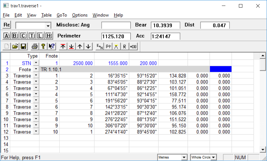
For larger looped networks there may be more than one loop. In this case it is essential that you learn how to define the traverse loop. To achieve this you need to enter a Fieldnote into the traverse table. Bring your cursor up onto the line defining 1 to 2 and make sure it is in the “type Column. Next Press the Insert Key on your keyboard, and you will see a new lien is inserted into the table. Pull down the options on this new line and select the “Fnote” type. Press Enter to lock in the Fieldnote and the cursor will move to the next column. The Fieldnote required to define the traverse loop is the letters “TR” followed by a space, and then a list of the points making up the traverse loop, separated by commas. In this case the, points are from 1 to 10 inclusive, and then back to 1 to close. The fieldnote would then be TR 1,2,3,4,5,6,7,8,9,10,1 or (TR 1,2,3 etc 9,10,11 if we define the end point as a new point) Since this requires a far deal of typing, and, since it is common to have a traverse made up of a sequence of points, we have implemented a method of defining a sequence and minimizing the typing required. Simply type the first point of the sequence, and full stop or decimal point, and the end point of the sequence, as seen in the alternative Fnote TR 1.10,1 So, regardless of how you decide to enter it, you need to enter it, and once you have done so you can now check on the misclose and accuracy of the traverse.
Calculate Misclose & Traverse Accuracy
You can either pull down the Option menu, and select Calculate Misclose, or, alternatively, select the button labelled “Re” (short for ReCalc) shown at the left of the second line. Either way the misclose, accuracy and perimeter should now appear in the relevant fields at the top of the screen as seen below. Now, in this case you should achieve an accuracy of closure of 1:24147 that is well within acceptable limits. Since you are within allowable limits, you may wish to adjust the traverse to form a perfect close, and if you so do, you can choose from the currently available adjustment methods of Bowditch, Compass, or Transit.
You may either pull down the Options menu, select Traverse adjustments, and then select your required method, or you can select the icons B,C, or T respectively. Either way you choose to do it, it is important to remember that the adjustments are made to the coordinate values of each of the points, and NOT to the raw information which you have observed in the field and entered into the traverse table. Once the adjustment has been made the program will advise you and inform you to use the Print to see the resulting adjusted values.
Calculate & Display Coordinates
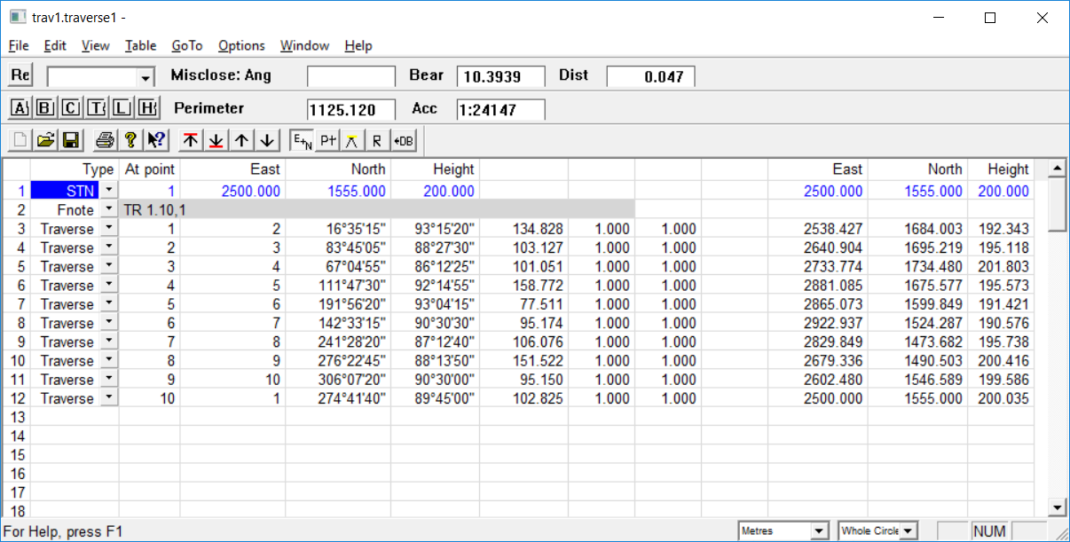
The aim of the traverse exercise is to eventually produce coordinate values for the traverse points (and any side shots taken from them) and to store these points into the job database. The first step in this process is to calculate the coordinates within the traverse sheet. Pull down the Options Menu and select Calculate Coordinates. Next, Pull down the Options menu again and select Show Coordinates (Or select the Icon with E+N on the toolbar. Once the coordinates have been displayed you can use the scroll bar on the bottom of the screen to shift the screen view to the right and display the coordinate values as seen below.
In this case you will see that the coordinates at the end of the traverse match those given for the start indicating that we have achieved a closed traverse. You should note that there is a small misclose of some 35 millimetres in the end height, and it is possible to adjust this out proportionally through the traverse stations if you wish.
Store Points To Database
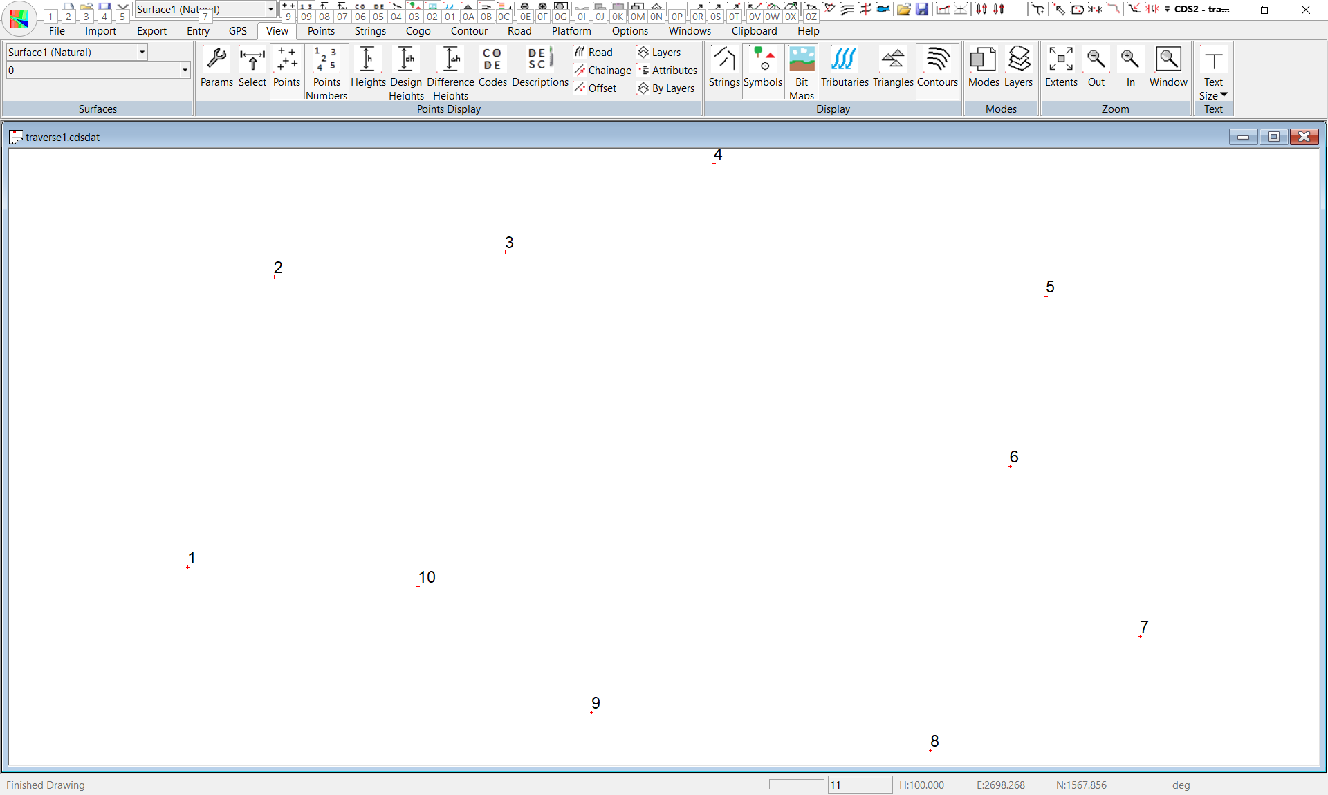
Now that you have arrived at adjusted values for all the points, it is time to store them in the database. Pull down the Options menu, and select Sore Points in Database. Then select all points and the points will be quickly stored. You should now use File Exit to close down the taverse entry sheet, and save any changes. You will see now that the points have appeared on the job screen as below.
Entering the traverse with observed angles
In this tutorial we show you how to enter in a traverse using angles. We first need to access the traverse entry screen. Use your mouse to select Entry from the options menu, and then select Traverse Network. Since this is a new traverse select the New option, and then maximize the screen. In this contrived example we are carrying out a closed traverse around a diamond shaped figure. Assume the first point (1) on the diamond has an easting coordinate of 1000.0 and a northing component of 1000.000 On the next line we need to tell the program that we have set our total station on point 1. Entering a backsight number of 0 ensures that the first shot will be a real bearing.
The next line is the traverse loop definition. As described in the previous traverse example the traverse definition is tr 1,2,3,4,1 The next line is a field note which tells us that the entries are in fact angles. The angle swing is by default measured in a clockwise direction from the last leg. In this example the defined traverse has been picked up in a clockwise direction. This means that the default angle would result in the external angle being measured. This is not a problem. In this example however we have picked up the internal angles and have measured the angles in a counter clockwise direction. To account for this there is a special field note that can be entered which simply say's anticlockwise.
A sketch of our data is shown below
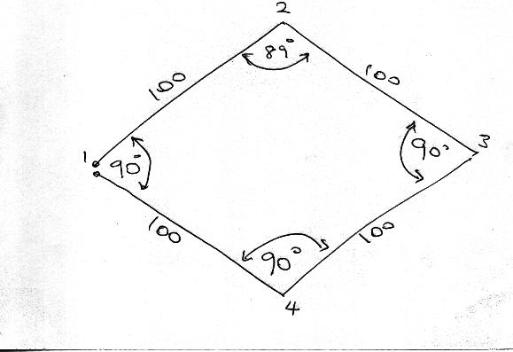
The data as entered into the traverse file is seen below. Please take note that the closing shot back to point 2 the second time around has been entered as a special "Close" case.
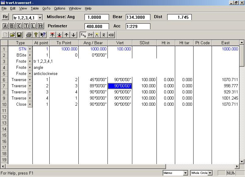
To calculate the angular misclose press the "Re" button. A misclose value of 1 degree will be shown. Pressing the "A" icon will distribute this misclose equally around the traverse. In this case the 89 degree angle is replaced with 89~15' and the 90 degree angle is replaced with 90~15'.
You may now perform bowditch, linear misclose as before.
|