| < Previous page | Next page > |
|
Display of utility data on road works sections
In this tutorial we are going to create the details for a water pipe on the property. We are then going to design a simple road. We will be able to view the water pipe details in the section view and modify our road design if appropriate.
Design of the pipe profile
In this white paper/tutorial we are going to design the layout of a water pipe that is to be layed. Please open up the job utilities found in the tutorial directory "c:\program files\foresight software\cds\tutor". If the data does not exist there you may download the file utilities.cab from our ftp site at ftp.foresoft.com If you have ftp'd the file you will need to restore the job with the restore archive facility. Open up CDS and then select Options->Restore Job.
If you open up this job you will have the following screen in front of you:
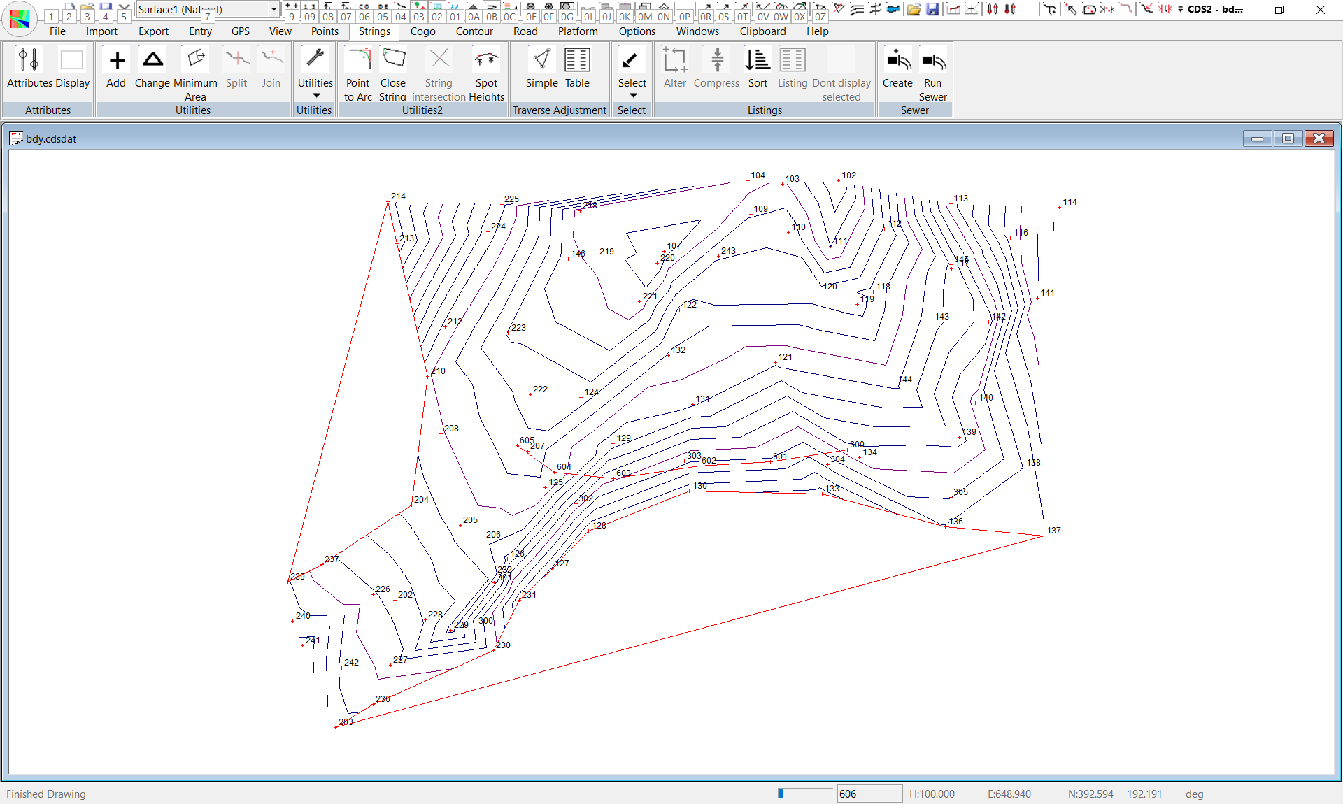
We have already included the string defining the plan view for the water pipe. It is found in the "lots" folder with a name of "pipe". It runs from points 600 to points 604 and is shown in red. To create a vertical design for our pipe we follow the procedure below which has been covered in previous tutorials.
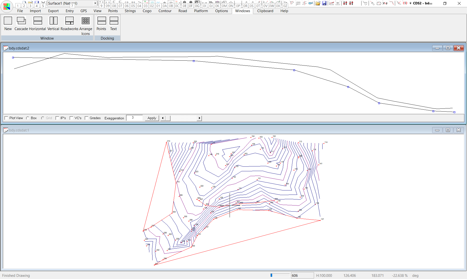
The screen shot below shows the vertical surface profile. We have added in our new vertical design. If you are unsure of the procedure please review the simple road design tutorial.
We need to set the interpolated profile points to take on the design calculated for our water pipe. This allows the program to pick up the appropriate heights of the pipe when we interpolate the profiles and sections for our road design. This is done from the menu item "Road->design surface->Store profile design points". This sets the design heights of all the points making up our profile string. We now need to put this profile string into the utilities menu for it to be picked up in our new road sections. Select the string in the profile folder and with a name of "cl_pipe" with the "Strings->Select->Select by range". Now click the "cut button" go OK and then select the "paste button". You are prompted for a change in folder name. Change the folder name to utility. We now have a string in the utility folder with a name of cl_pipe. All the points on this string have both a natural and a design height. The design height is the actual height of the pipe at the particular point.
Design of the road
If you are not sure of the basics here we suggest that you review some of the previous road design tutorials. Especially the simple road tutorial. The method used in point form is
You should see a section view such as that below:
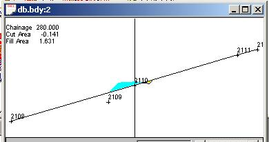
In this case we see that point number 2109 is not included in the section; but is shown as a fixed point. In this case it would be nice to display a circle at the appropriate size to indicate that it is indeed a pipe. There is indeed an option to achieve this and it is done through the feature code routines.
To help in the display of utility sections you need to fill in a special feature code library called "section". This tells the road sections view how to display the appropriate symbol in section view. CDS is supplied with a special symbol called circle that represents a circle that has a diameter of 1 meter. The feature code library can be filled in as follows:
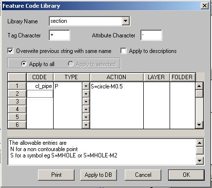
For this case do not hit the "Apply to DB" button. Simply press the OK button. If we refresh the section view we now have the following
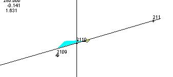
A circle drawn at 500 mm can be seen. Please note that the circle is scaled relative to the horizontal scale. In this case the vertical exaggeration is not applied so please keep this in mind.
To complete the design we need to do the following:
|