| < Previous page | Next page > |
|
Volume between two surfaces
In this tutorial you will learn how to:
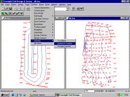
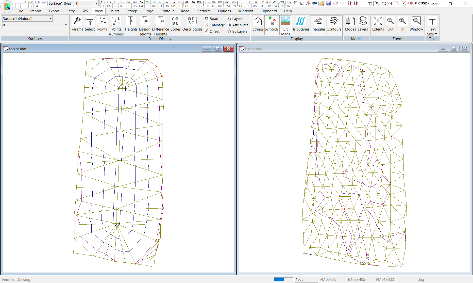
Your client has come to you and informed you that he will soon be having road construction materials delivered to his storage compound, and that he will need you to calculate the volume of material available from time to time. You have sent the field party out immediately, and they have picked up the area where the gravel will be stored, and this data is in job BSE supplied in the Foresoft\cds3\tutor folder. Once the gravel has been dumped, the field party returned to the compound and carried out a detail survey of the gravel heap. This information has been supplied in job TOP in the ‘Foresoft\cds3\tutor’ folder. Start CDS and use File Open ( or the Open Icon) to open Job bse in the Foresoft\cds3\tutor folder. Next, use the Open command again to open top, also in the ‘Foresoft\cds3\tutor’ folder. The screen should appear as below.
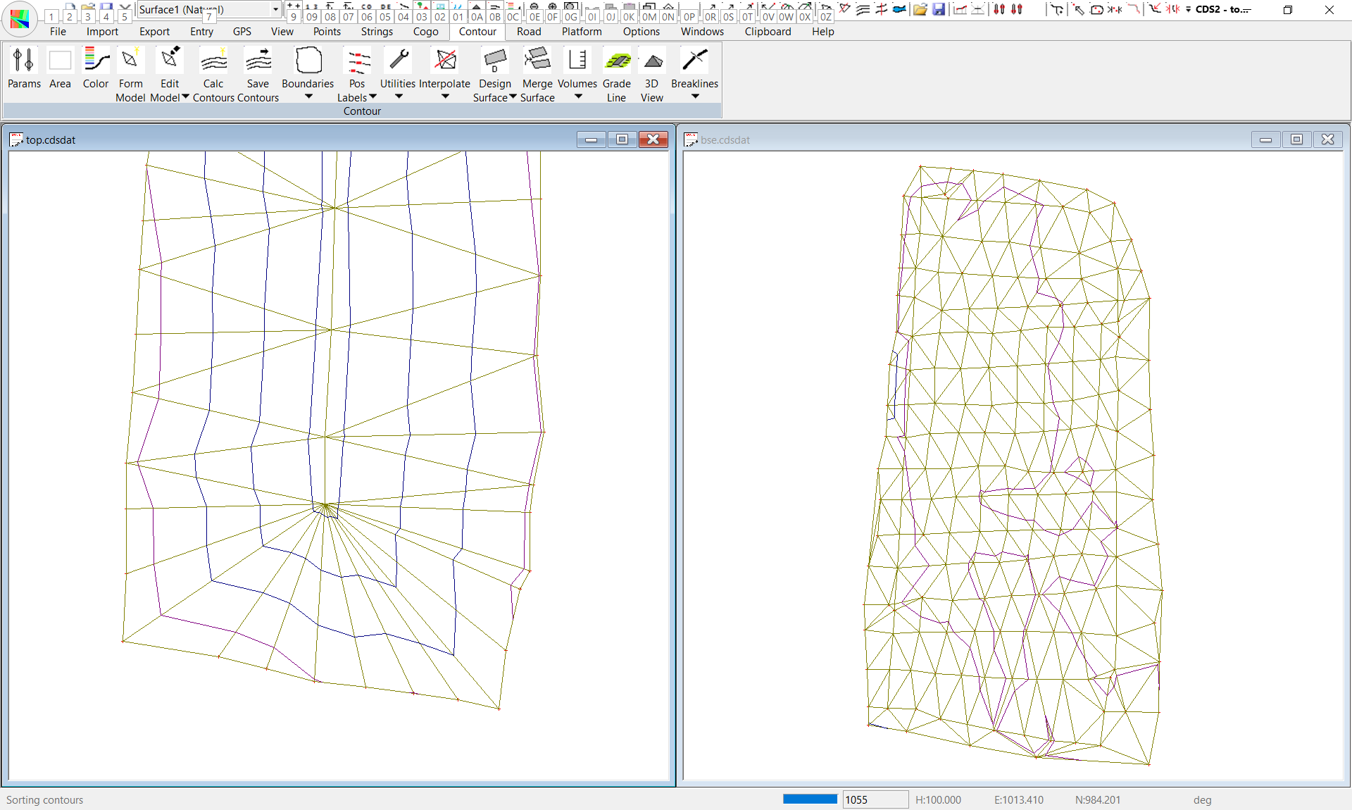
Now pull down the Window Menu, and select the Tile Vertical option. Your screen should now appear as below right. (You might need to Zoom Extents on each window if they do not appear as shown)
Make Job ‘top’ active, and pull down the Contour menu and select the Surface Parameters option. Change the major interval to 2.0 and the Minor interval to 0.5, then click OK to close the parameter screen. Now pull down the Contour menu again, and select Form Model.
The triangles will quickly form over the surface. Once the triangles have been formed, pull down the Contour menu again, and select Calculate Contours. When the contours have been drawn you should elect to save them. Press F8 to turn off the triangles.
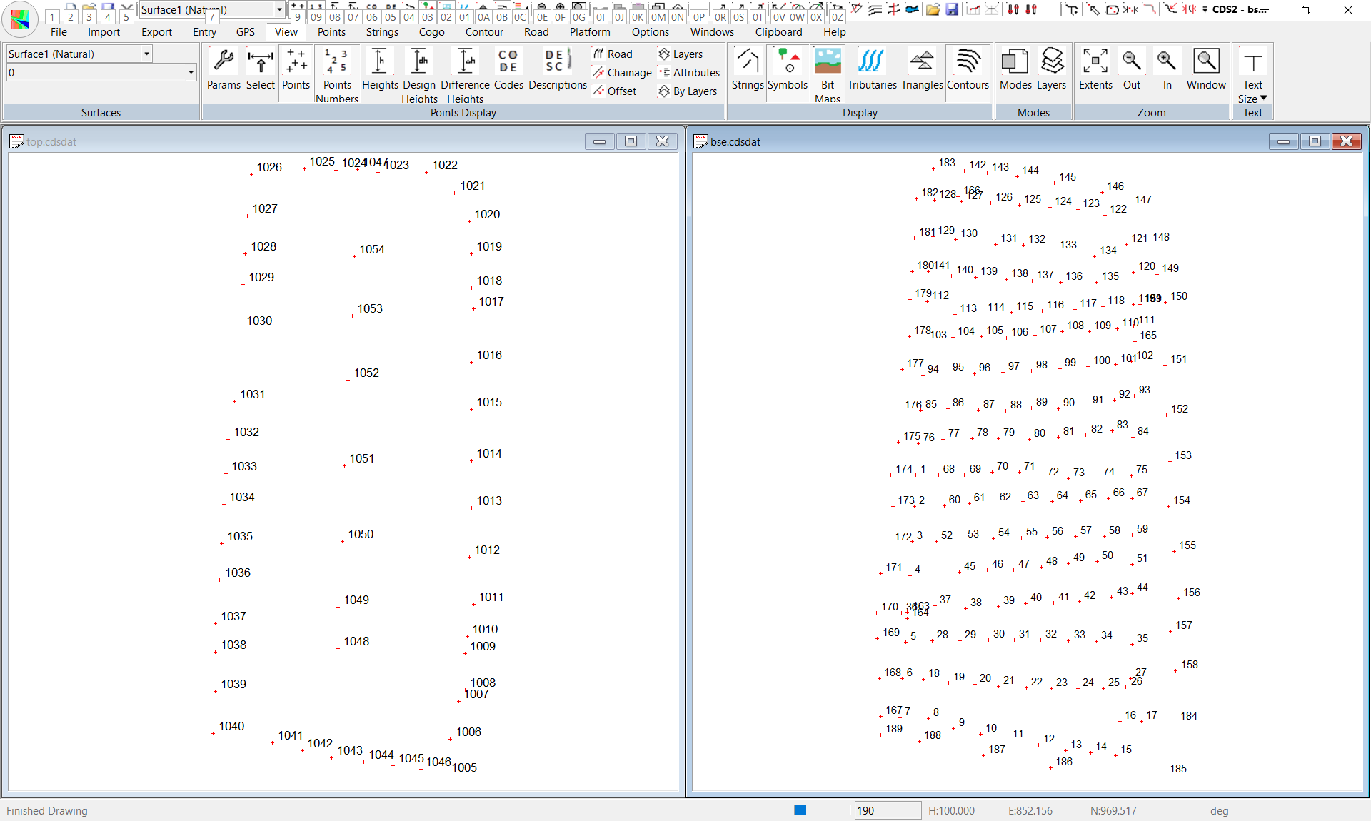
Now you need to make job ‘bse’ active. Position the cursor inside the window containing job ‘bse’ and press the left-hand button on your mouse.
You will see the bar at the top of the window becomes coloured while the corresponding bar in the left-hand window is greyed out.
Pull down the Contour menu and select the Surface Parameters option.
This job represents a reasonably flat base area, so if you are to see any contours at all you should change the major interval to 1.0 and the Minor interval to 0.2, then click OK to close the parameter screen. Now pull down the Contour menu again, and select Form Model. The triangles will quickly form over the surface. Once the triangles have been formed, pull down the Contour menu again, and select Calculate Contours. When the contours have been drawn you should elect to save them.
Press F8 to turn the triangles off, and the screen will now appear as seen below.At this stage, both surfaces appear to have been successfully modelled, so it is time to calculate the volumes. Pull down the Contour Menu and select the Volume option.
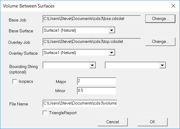
In a later tutorial, once we have made you familiar with the different process required, we will introduce you to the concept of specifying different surfaces within a job.If you look at the screen in front of you, you will see that the base job is specified as ‘db.bse’. You will need to change the base job to bse. Select the Change button, and then select bse.cdsdat from the Foresoft\cds3\tutor folder and select the Open button (or double click top.cdsdat).
However the overlay job is shown as ‘top’ so there is no need to change anything here. At this stage we are not interested in Isopachs, and we want the volume results displayed on the screen and saved to a file called “Pile1.rtf”. Position your cursor in the File field and enter “pile1.rtf” as the name of the file. Once this has been completed, select the OK option and the results will soon appear as seen at right, where the results appear in Wordpad showing an amount of some 11,970 cubic metres of material. You might think you can just print this out, hand it to the client and collect your fee, however, before you do that it is important that you look carefully at the results presented, and think about what is being presented.
You will notice that the answer suggests that there is an amount of Cut of almost 25 cubic meters in addition to the Fill volume presented. Some people might be inclined to subtract that Cut amount from the Fill amount to achieve a nett result. This debit and credit scenario may be adequate accounting practice, but it is appalling surveying practice, and it would be totally wrong in this case. We know for a fact that the gravel was simply dumped on top of the base surface, and that the base surface had not been disturbed before the dumping took place.
In that case, quite simply there should not be any “cut” involved in the job, so we need to look back at the surfaces , or more particularly the “Top” surface, to see what has happened during our modelling process. You should make sure you are logged on to job Top, and then set your surface parameters to give a major contour interval of 1.0 with a minor interval of 0.1
Calculate Contours with these values, and then zoom in on the bottom section of the job, as seen in the screen at right. You should notice a “slightly funny” contour occurring on the bottom right of the stockpile (and also on the bottom left if you look closely). There is sufficient deviation from a well formed stockpile here to warrant a closer look, so use the F8 key to turn the triangles on, and you will see that the triangle sides in this area do not run from the crown of the heap down to the base as you would expect.
If you now use F7 key to turn the contours off, you will see from the screen at right that there are at least three triangles in the bottom right corner which do not represent material falling from the crown of the stockpile down to the edge. Likewise, in the bottom left hand corner you have a similar situation. (and the same thing occurs in the Top Left hand corner of the surface as well.)
Now, before you become excited and accuse the program of getting things wrong, remember that it has never seen the job, so the answer it has presented you with is mathematically perfect, even though practically inappropriate.
It is up to you to reform these triangles to ensure that they are correct, and to that end we have given you the tools under the Edit Model option on the Contour menu.
You could go about correcting the triangles either by selecting all the erroneous triangles, Deleting them and then using the Add Triangle option to add the triangles in the configuration required.
Alternatively, you could select the two adjacent triangles formed by points 1048,1007, 1045 and 1045, 1007,1006 and then use the Swap Triangle Sides option to make sure a triangle side runs from point 1048 to 1006. Once you start selecting triangles use the right mouse menu. It is faster than the drop down menu at the top.
Next you should concentrate on the top left hand corner of the job to perform a similar correction exercise and end up with a triangle side from point 1054 down to point 1026. Once you have finished with these major corrections, you can run the volume calc again, and you should get a slightly different result of 11,604 cubic metres of fill, with still 7 metres of cut. Now at this point, you need to consider whether you treat quantity surveys as a precise science (which I do not), or whether you are prepared to live with an “error” of around 0.05%. And, before you panic about having work with an “error” in it, I strongly suggest that you reflect for a moment on the nature of the process and ask yourself whether it is ever practical in a field situation, to obtain an “absolute volume”. If you wish to strive for perfection, (and on this set of data it is probably valid to do a little more fiddling around the edges) then I suggest you have a close look along the edges of the stockpile. Look particularly around point 1007, 1008 and 1009, and swap triangle sides around where necessary, and delete some extraneous triangle if you think it is warranted.
The point of this exercise is that the computer is merely a tool - it is NOT an intelligent being, and it cannot analyse the answers for you.
You MUST NOT accept any answers which the computer gives you, particularly in the area of volumes, without THINKING about the answers, and their application to the real world you work in. It is your responsibility to interpret the answers provided, and apply them to the data used.
Neither Foresoft Pty Ltd, nor its agents can or will accept any responsibility for the answers YOU produce with the software, or the manner in which you use those answers!!
|