| < Previous page | Next page > |
|
Importing Data from Other Software.
The function of this exercise is to show you how to;
Start a New Job
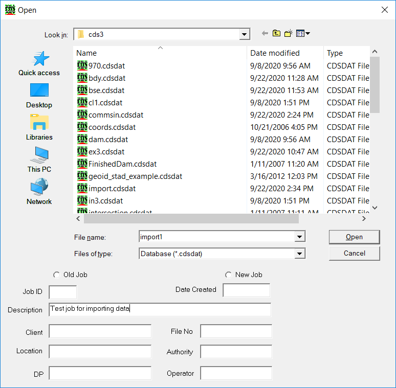
Start CDS and use File New to start a new job called ‘import’.
Since we will only be working with one job, you should maximise the screen. You have been sent a file from your colleague who did the field survey, and in this case she has told you that she has supplied you with a civilcad ASCII file called ‘surface1.asc’. In real life you might equally have been given a MOSS Genio, or a Geocomp file. What is important here is to learn the process so that you can later apply it to particular circumstances, and the process is essentially the same regardless of the origin of the file you need to import.
Import the File
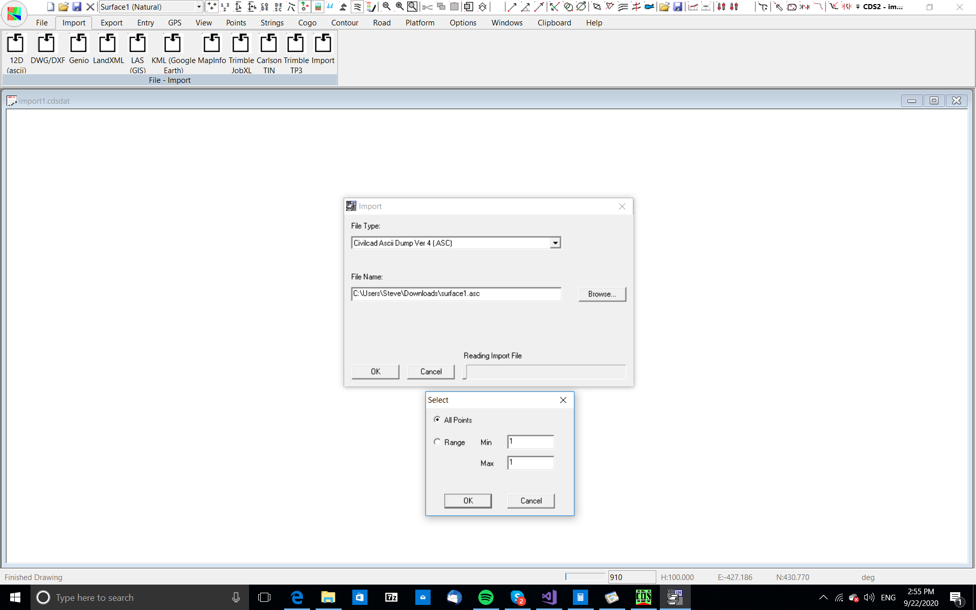
The first step in the process is to import the file called ‘surface1.asc’. Pull down the File menu, and select Import. Use the pull down File Type option to select a Civilcad ASCII File Ver 4.
You will see the action bar along the bottom fill in as the points are imported.
Next CDS will inform you that it has found strings in the ASCII file, and ask if you wish to import them. Select Yes.
CDS will now ask you to provide a string folder to store these strings in.The folder name is of no great importance, as long as you use a name which makes sense, and here, since the strings have originated in the field, I suggest a folder name of ‘field’.can see from the screen above.
Form Model & Contour
At this stage you need to form a contoured model, and while these steps should be very familiar to you by now, I will repeat them to reinforce your memory.
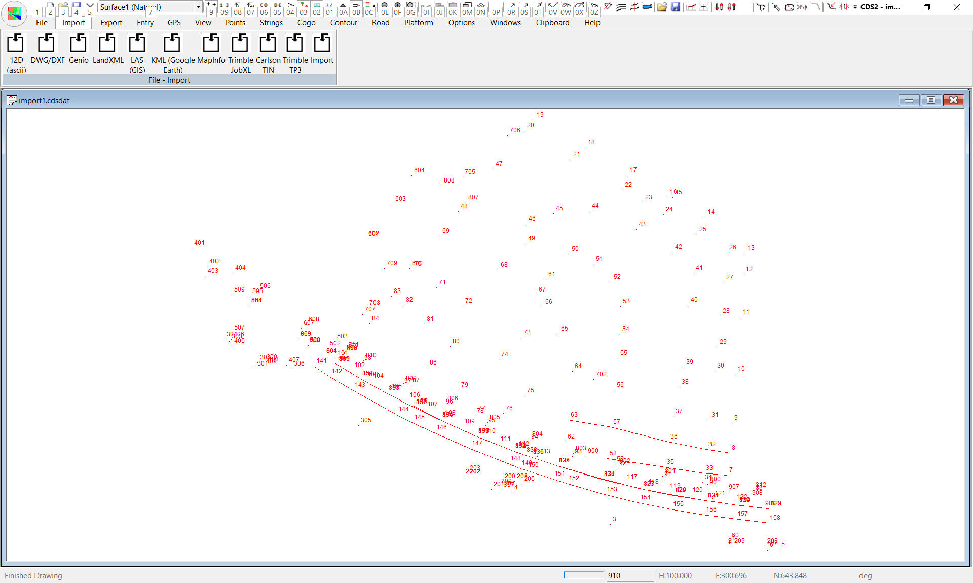
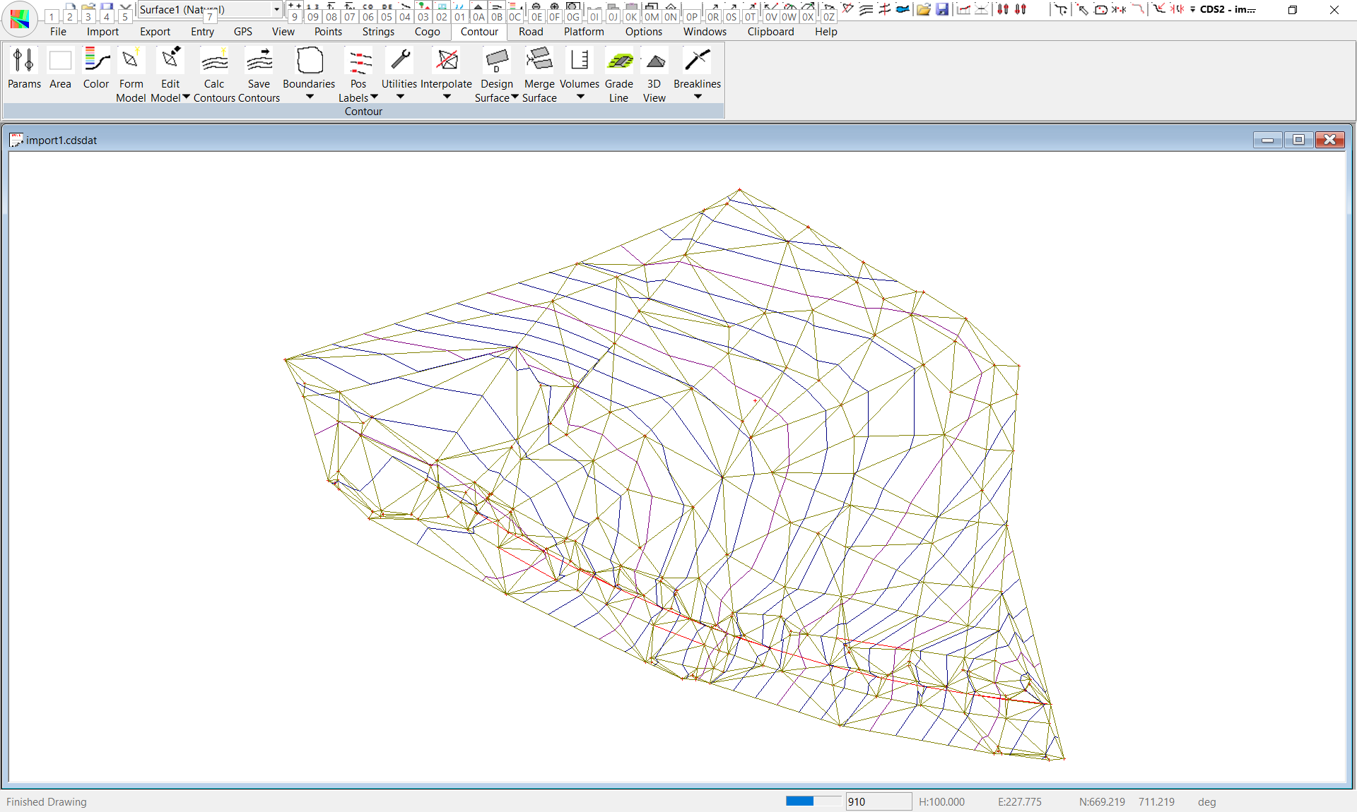
Pull down the Contour menu, Select Surface parameters and rest to pick up the extents of the job. Now change the Major Contour interval to 2 metres, and the Minor Interval to 0.5.
Pull down Contour, Select Surface area, and select Extents. Next form the Model.
Importing From CAD.
It is common to be given a CAD drawing which has the design layout that you need, and you will need to import that information into CDS.
Some Cautionary Warnings
Please NOTE that it is important to try and ‘control’ this information at the CAD stage if you possibly can, because it can save you hours of subsequent ‘sorting out’. It is usual for the architect or engineer who is doing the overall design to have a reasonably complicated drawing with all manner of things shown, including underground utilities, internal walls in buildings, overhead power lines, and fanciful landscaping, not to mention wonderfully ornate borders and title blocks. It is also usual that you are really only interested in bringing a few of these things into CDS. If the CAD operator has placed different things on different layers, then it can make your task simple if you can ask the CAD operator to turn off or freeze all the layers that do not interest you. Even better to get the CAD operator to actually ‘extract’ or copy the layers that do interest you into a separate drawing, and then simply give you that ‘smaller’ drawing to process. I should also warn you that because of the way in which CAD packages construct polylines, it is quite common for you to get double the number of points which you actually need when the data arrives into CDS.
And, as a final note of caution, if someone suggests that they give you a DXF, please ask them if you can have the DWG file instead, as it is considerably smaller in size and therefore quicker to process.
OK, enough of the warnings and on with the job.
You will have been supplied with a file called ‘lotdwg.dwg’ which is an Autocad® drawing file in which one of your colleagues has designed a proposed layout for a subdivision on the land you have modeled earlier.
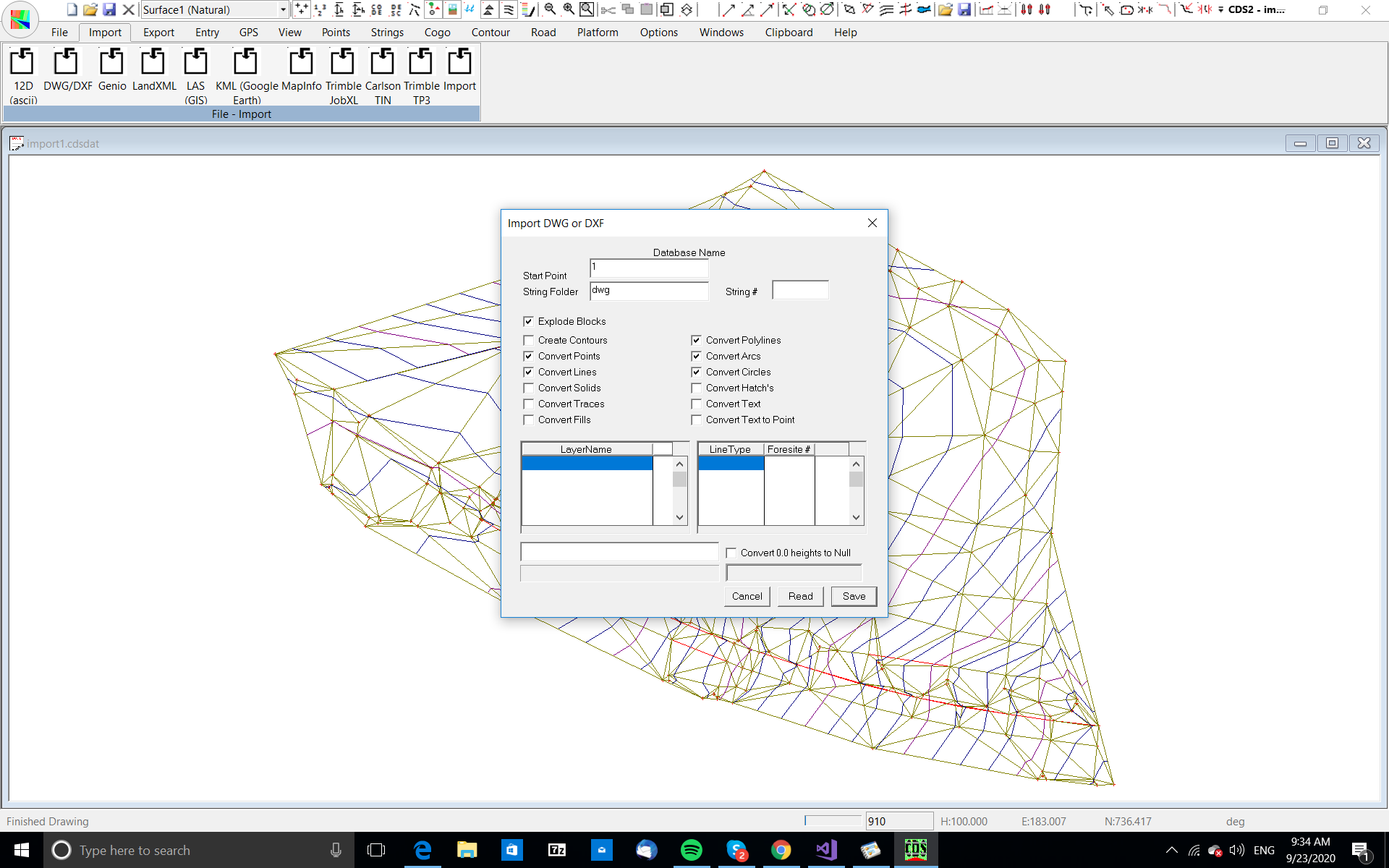
Select the File menu, and then choose Import DWG/DXF.
Now the screen will appear as seen above.
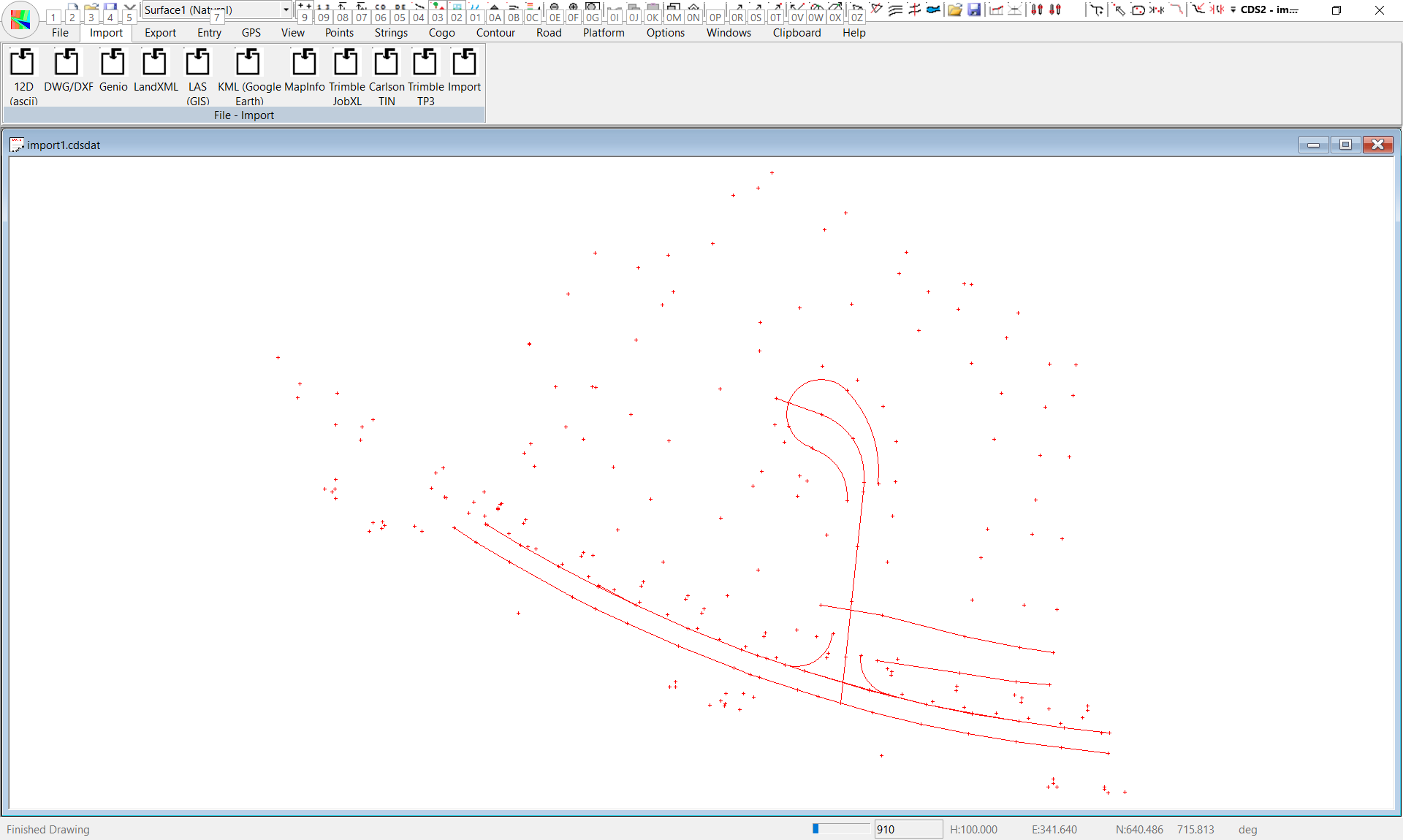
Press the Save button and you will find that CDS reads through the drawing again, and this time stores the points and strings into your job. Once the screen re-appears, press the F8 key to turn off the triangles, and the F7 key to turn off the contours and you should be able to see the outline of a cul-de sac.
Removing Duplicate Points
Pull down the Options Menu, select QA Routines and then select Filter Duplicate Coordinates.The screen will be similar to that adjacent, and you need to uncheck the box ‘Keep Points Used in Strings, since all of the offending points in this case are in strings.Next you should check the button titled Delete Higher numbered one, since this is the most effective method of dealing with CAD induced duplicates.Press the OK button and the program will go about its task.
Once this is completed, you will see that the strings remain in place, but the ‘double’ points have disappeared. You can now use these strings to interpolate profiles and sections across the surface.
|