| < Previous page | Next page > |
|
Cul-de-sac and Intersection Design
Design procedure 1 will involve a design along the two sketched center lines. Very much how we design a straight section of rural road.
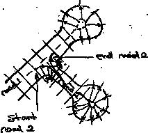
Design Procedure 2 will show an alternative design procedure. In this case we do a profile design along the center-lines of each road. We then design along the continuous curve that runs around the whole structure.
Horizontal Alignment and Cul-de-sac Design
We need to design the road / structure in plan view. This would normally be incorporated into a larger subdivision design and road easements would most likely already be defined were these roads can fit.
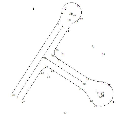
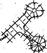
We have supplied the job culdesac. This job is supplied with some background height data as well as 3 strings defining the two road center lines as well as a string defining the kerb that runs around the two cul-de-sacs. The following describes how we arrived at this point.
First we need to define the position of the Road1 center line. We have been given the coordinates of the start point1 (E231.417,N375.753) and the position of point 2 (E250.078,N404.592) which is the start point of the cul-de-sac. Enter these points by using the “Points” menu and then “Add”. Click the points in and modify there Easting and Northing to the exact value. Create a string in the road folder with an ID of cl1. If you are not sure about how to do this we suggest that you look at the introductory chapters again.
Vertical Road Design
We now need to create a vertical design for both roads and the associated cul-de-sacs. The traditional approach to follow is :
Below we have two sketch's
We still need to worry about the intersection design which we have ignored. We are going to need to do something eventually. We have a number of options here -
As we can see there is no right and wrong way to do any of this. We simply supply the tools which hopefully makes your job easier. For a small design like this in reality the dozer driver would probably not even need the intersection design.
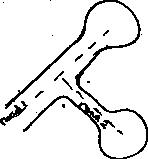
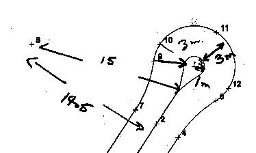
First bring up the job as created in the horizontal alignment. The job name was culdesac1. Our first step is to create the small arc around the center of the cul-de-sac. We have sketched here the relevant cul-de-sac dimensions and how we intend to design in the small arc at the center of the cul-de-sac.
We need to design a couple of points to define the mini center. The radius of the cul-de-sac is 4 m's. We have decided to have the arc in the center to have a radius of 1 m. Please use your own numbers here. Therefore the distance from outside of this center arc to outside of the cul-de-sac is 3 m's. The distance from point 8 to point 7 (lead in radius) is 12 m's. Therefore at the point the center starts is 15 m's from point 8.
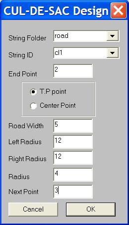
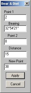
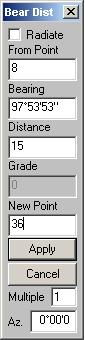
Our first step is to define the position of this point. CDS contains a function to calculate the intersection of a bearing and a distance. In this case we wish to find the point that lies 15 m's from point 8 and also lies along the line from point 2. From the "Cogo" menu and then "Bearing and Distance Intersect" sub menu and then "Bearing & Distance Int" menu item. Fill in the dialog as below.
We now need to calculate the end point of this arc. This point lies along the line joining 8 to point9 but extended so it is at a distance of 15 m's from point 8.
We now need to calculate the out going point on the center structure of our cul-de-sac. ie the point 15 m's from point 5 and in line with the line joining 5 and 6. Use the Cogo -> Radiate menu item to calculate it and call it point 37.
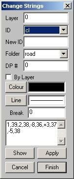
Next step is to re-define the center line point to include these new added points. From the "Strings" menu select the "Change" item
We are now in a position to design this road and cul-de-sac in the same way we easily define our traditional rural road.
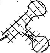
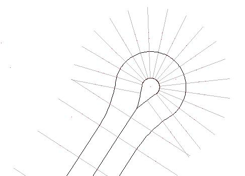
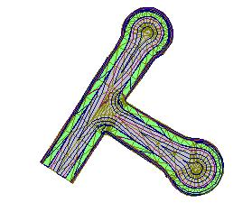
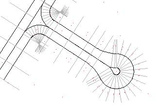
We first need to interpolate profiles and sections along the line. Use a distance left and right of 8 meters. We can create sections along the straight every 5 m's and a distance of 1 m around any arcs. Once this has been run refresh the screen ( Simply single click the center button on your mouse. ze for zoom extents has a similar result. You will see the position of the sections drawn in light grey. First thing is that on sections around the arcs we have sections left and right. For these we only want the section on the left. To de-clutter the screen (this is optional) we need to delete any points with positive offset if they are on an arc.
We can do this from the appropriate section view. First show profile view - ie click on the profile view icon. Show the section view by clicking on the appropriate icon. From Windows menu do the "Tile Roadworks" option to display the 3 views of our road.
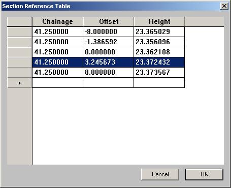
To tidy up this section click into the section view. Now right click and select the reference coordinates menu item. It shows a table with all the points in this section. We prefer to delete the points with an offset of 3.24 and that at 8. Simply click into the left most column and the whole row is highlighted. Hit the delete key and keep hitting it until all the appropriate points are deleted. Do this for any appropriate sections.
Once we are happy with sections present we can do the profile design. As this is the major of the two roads we don't have too many design constraints. The only one being maybe the start if we have to tie that end in with an existing or more major road. We have created the profile design as below. Note that to simplify drainage requirements we have designed the profile so that it slopes upward from the start:

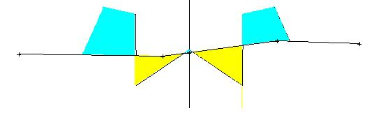
Next step is the section design. For this design we wish to grade along the appropriate section until we hit the kerb string line; go up to the top of the gutter; draw in a footpath and then grade to the natural surface. At present you need to be running a version of CDS Premium later than mid September. Below we have the section as designed in the "Standard Templates" sections as well as a typical section in the job.
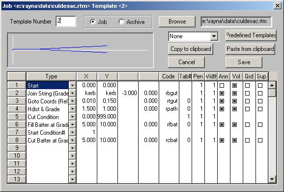
For those sections where we have templates left and right we have template 1 on the left and template 2 on the right. Template 2 is slightly different in that the point codes of the points are prefixed with a r to indicate we are on the right of the road. Also we don't annotate the center point; otherwise it would be in the job twice.
Template 1 (Left Side)

Template 2 (Right Side)
Design of Road 2
As mentioned earlier we are going to include the intersection design into the general design of road2. To this end we need to define a lead in arc that runs from the road1 alignment onto the alignment for road2. The center line is then going to travel down to the cul-de-sac bulge and return and join back onto road2 via another arc.
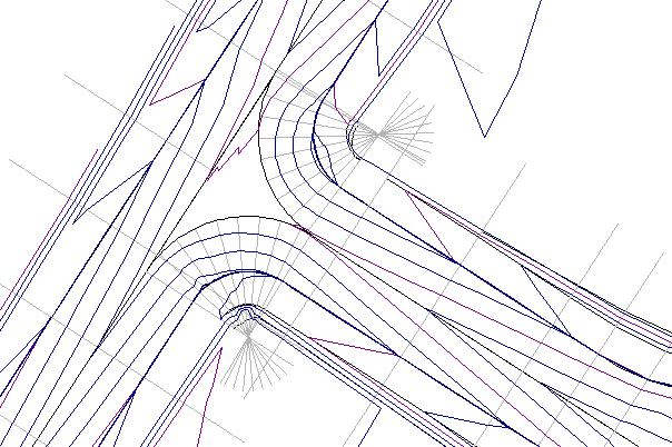
We now need to define the bulge center arc as we did for road1. We will not repeat this here. Please look at what we did on the end of Road1 if you have forgotten. As per road1 lets us now create some sections and profiles along this Road2. Remember to have natural triangles shown and not the design triangles. We have created sections every 5 m's along the straights and 0.25 meters around the arc's. As per Road1 edit all the sections so around bulge so we only have sections to the left. On incoming arc in intersection only use sections to the right and end arc to the right as well. In plan view our sections are as follows:
We can now do our profile design. There are a number of constraints we need to be aware of.
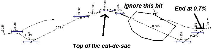
We need to go back to Road1 to get some of these values. Select the Road1 center line in "Strings -> Selection -> Single String Selection. Then click on the big green P button (Natural Profile Definition) Replace listed string by pressing the "Replace with Selected Strings". Do for the "CS Reference" dialog as well. Now display the profile view and tile the views. Zoom up around the intersection in the plan view. You can then move your cursor along the profile to the intersection points and by inspection get the heights and grades. At the start we have a height of 23.285 at a grade of 0.3% and at the finish we have a height of 23.320 at a grade of 0.7%
The profile design is shown below. To satisfy the start requirements we clicked in a point at chainage 0. Display the IP table at enter in height of 23.285. Calculate a new point along at a grade of 0.3%. We also set the point at the end of the start arc to be down at a grade of about -1%. We need some sort of negative grade here otherwise the main Road1 will have a big bump in the middle. Depending on the relative importance of the two roads we can adjust this accordingly. In the profile design below the high point was the top of the cul-de-sac and we have set the in and out chainages of the cul-de-sac middle to be the same height..
On inspection our design may lead to some problems with drainage around the intersection area. Not being an experienced designed I am not sure so lets continue and view the final contours to see what happens.
We will use very similar templates to Road1. We have used Template5 on right, Template4 on left and Template3 around the bulge. Template1 and 4 are identical except in Template4 we have not annotated the center line point. Template5 and Template2 are the same except we have annotated the center line point in Template 5.. After running triangulation and contouring with 0.025 interval we have the following contours. We have a relatively smooth transition between roads
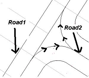
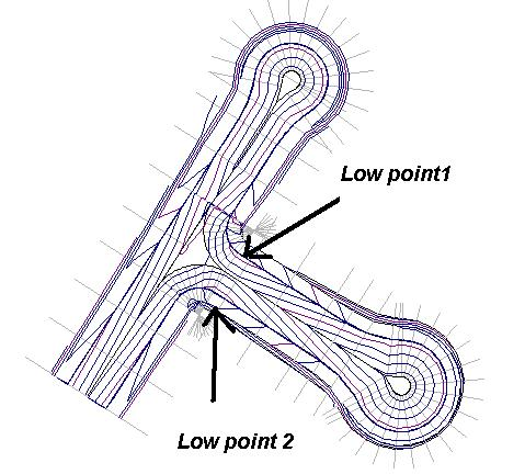
We now need to create a design surface which incorporates both roads. Create a new design surface so that we don't lose previous surfaces. You may re-use existing design surface if you wish; it is up to you. We have created a new surface 4 and the result is as below. We needed to create a break-line between points 20032,20041 and 20050 to clean up the triangles in the intersection area. The triangles were trying to creep across the center line. On the diagram below I have shown two area's which are low points - ie water will accumulate here. At low point1 there is little we can do other than continue the gutter across the entrance to Road2. (This is a low cost option if Road2 is not used too much) Low point2 is a little different. If we are happy with what we have road design wise we may add in a storm water run-off pipe that collects from Point2. Otherwise we need to redesign our intersection. We could
Who noticed the problem in the contours above. Going out from the end of Road2 we appear to have a problem joining back onto Road1. The problem was some design points on the right of Road1 that cut across between some of the design contours for Road2 were it joins on. To fix simply delete the 5 design points from Road1 at this point and only use those from Road2. The contour plan below was designed by raising the design profile of Road2 by about 50mm at the appropriate place. As mentioned we now have water run-off but our intersection design is probably not as good. Please remember however that we are plotting contours at 25mm so I would suggest for a small not very well used intersection that if is probably good enough.
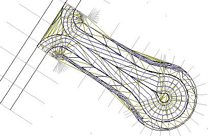
CDS also allows the 3D view of the job. I have included screen shot below. With the colors selected it is more of a visual check that we have not stuffed something up.
 |