| < Previous page | Next page > |
|
Road Widening
A common road design problem is the widening and repair of existing road surfaces. In this scenario we wish to fill in the road shoulder and possibly widen the road as well on both sides. To minimize the cost we don't want to change the existing pavement.
The data will be found in the tutorial directory, the data is supplied in the job 'roadwidening'.
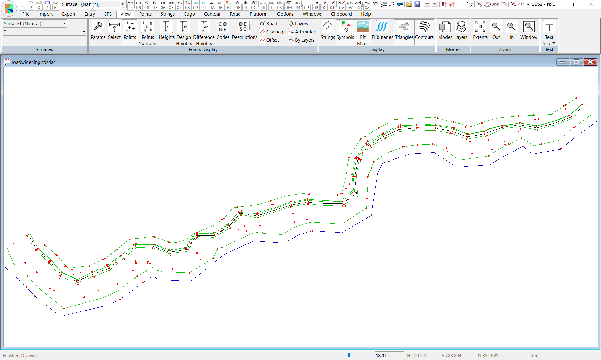
In the following example we have an existing forest road which we need to widen to 3 meters on either side of the given road center line. The field party has picked up points nearly in sections and has also defined for us three strings. These strings are
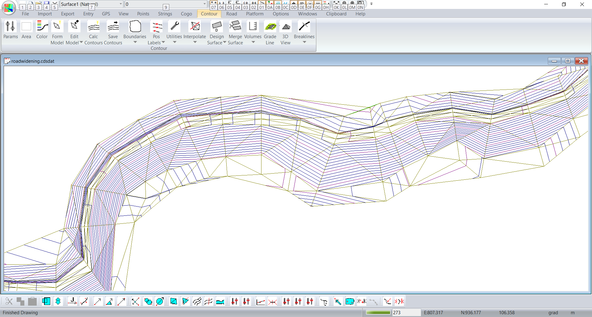
The first step is to triangulate and contour the surface and check that what we have adequately represents the existing road and surrounds. If you are unsure of how to do this we suggest that you review the procedure found in earlier tutorials. We need to use these strings as breaklines to stop triangles forming across the existing road surface. The data as supplied has had this done. The screen shot below shows a section of the road that has been enlarged. It is suggested that you first pan along the road to check that everything is OK before proceeding.
This is what we have after creating contours:
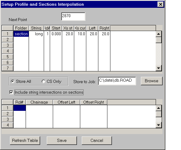
We now need to interpolate some sections from this surface. From the "String" menu use the Select - Single string option to select the existing center line. Once you have done this run the "Interpolate Profiles and Sections" from the "Contour" menu. The interpolated points are placed in a separate table separate from the main database.
Once you are happy with the sections produced accept them. We are now in a position to start the design process of the job. The interpolated road becomes the current active road.
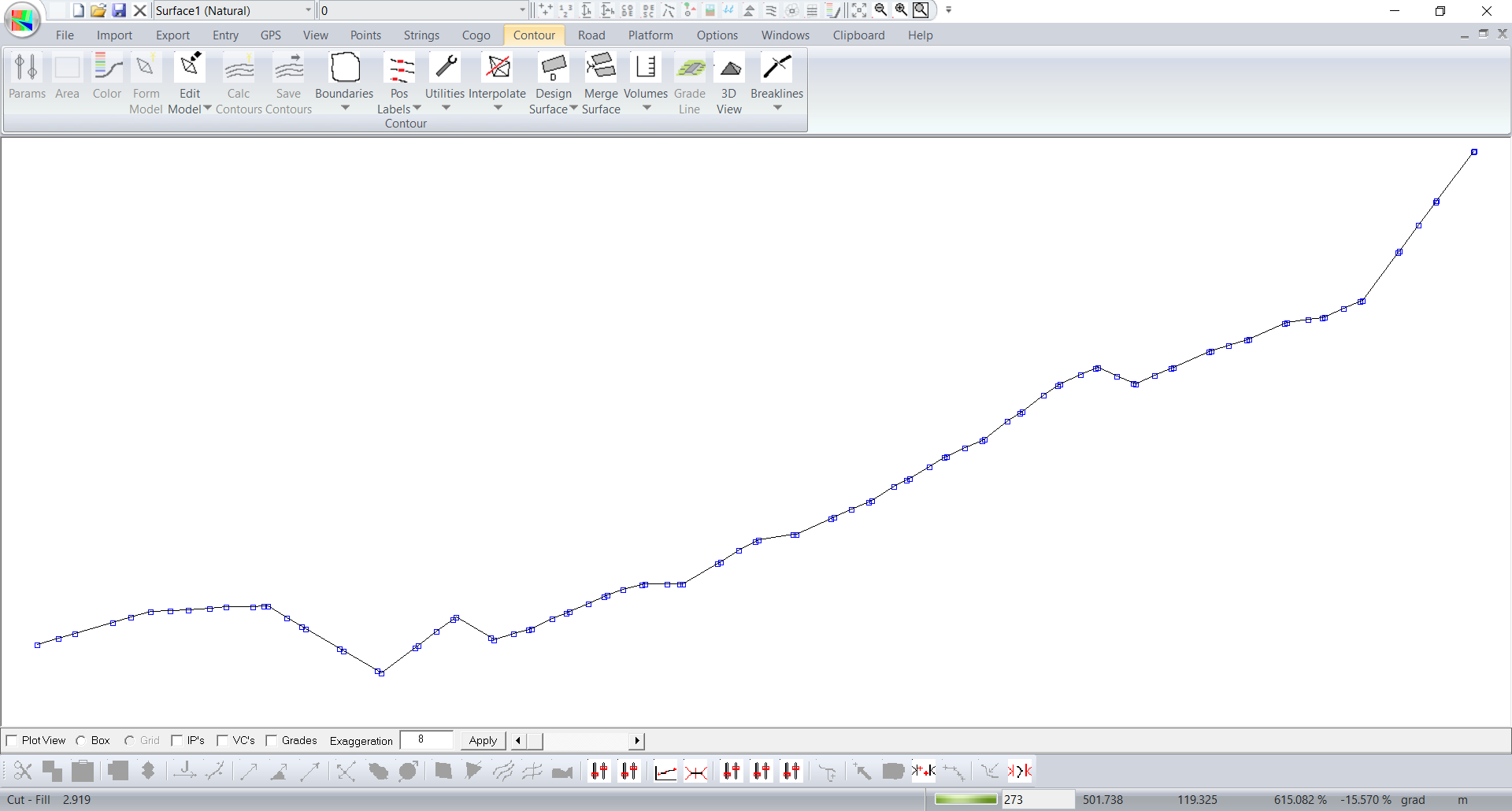
We can now display the natural center line. The next step in the process is to design a new vertical alignment. In this case we are keeping the existing road. The design is simply what we have. To achieve this show the profile and right click with the mouse. On the pop up menu select the "reference line to design" option. The program picks up all the points and uses there chainage and height to fill in the design. Thus the design and the reference line are displayed on top of each other. The profile can be seen below:
Summarizing so far. We have created sections along the road. We have extracted the profile of the center of the road. The next step is to define a road template that specifies our design section.
Specifying the design template
From the "Road" menu select "Design Criteria" and then the standard template option. Select template 1. We will hang this template to the left. The first command is a start command and we will specify X and Y values of 0.0 to signify that the template is hung directly of the center of the road. We wish to maintain the current road section so we wish to join straight across to the left edge of the road. The string along the left edge of the road defines this existing edge. This is achieved with the "Join String Natural" command. ie Join a line to the existing string in folder road and ID left. From here we wish to widen what we have until we reach an offset of 3 meters. ie the total width of the road will be 6 meters. We use the "Offset & Grade" command. For the offset we specify 3 meters. However we don't know the grade. Specify a value of 99999 or greater. The program accepts this as a special case and automatically uses the grade of the previous leg. Once we reach the new edge of the road we will put in the appropriate batter slopes depending on whether we are in cut or fill. The completed template definition for the left hand side is seen below:
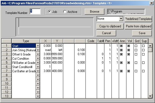
We need to create a slightly different template for the right hand side. In this case we create a standard template 2. The only difference is the "Join String (Natural)" command. In this case we wish to join to the right edge of the road defined by the string on Folder road and ID right. The next step is to specify that we are using template 1 on the left and template 2 on the right in our template positioning table.
Display one of the sections by clicking on the section icon. It is 16 across from the left on the bottom line of icons. If you right click in the section view you will see the menu item "Template positioning". There will be 2 columns displayed. 1L and 1R which are for left and right respectively of design line 1. Fill in a template of 1 to the left and 2 to the right. You only need to fill in the first line. Once this has been done right clicking on a current entry will fill in the rest of the column with the same number.
Displaying the next or previous section will update the section displayed and we should have a typical section such as follows:
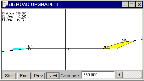
As we can see the new design runs along the existing surface but comes out until we reach an offset of 3 meters. We then apply the appropriate cut or fill batter.
Now look at the plan view road display. The are a couple of issues around the changes in alignment. To be honest most roads have smoother transitions so you don't normally have issues such as this. However if you look at the screen shot below you can see that the sections are crossing over and some of the more severe intersections:
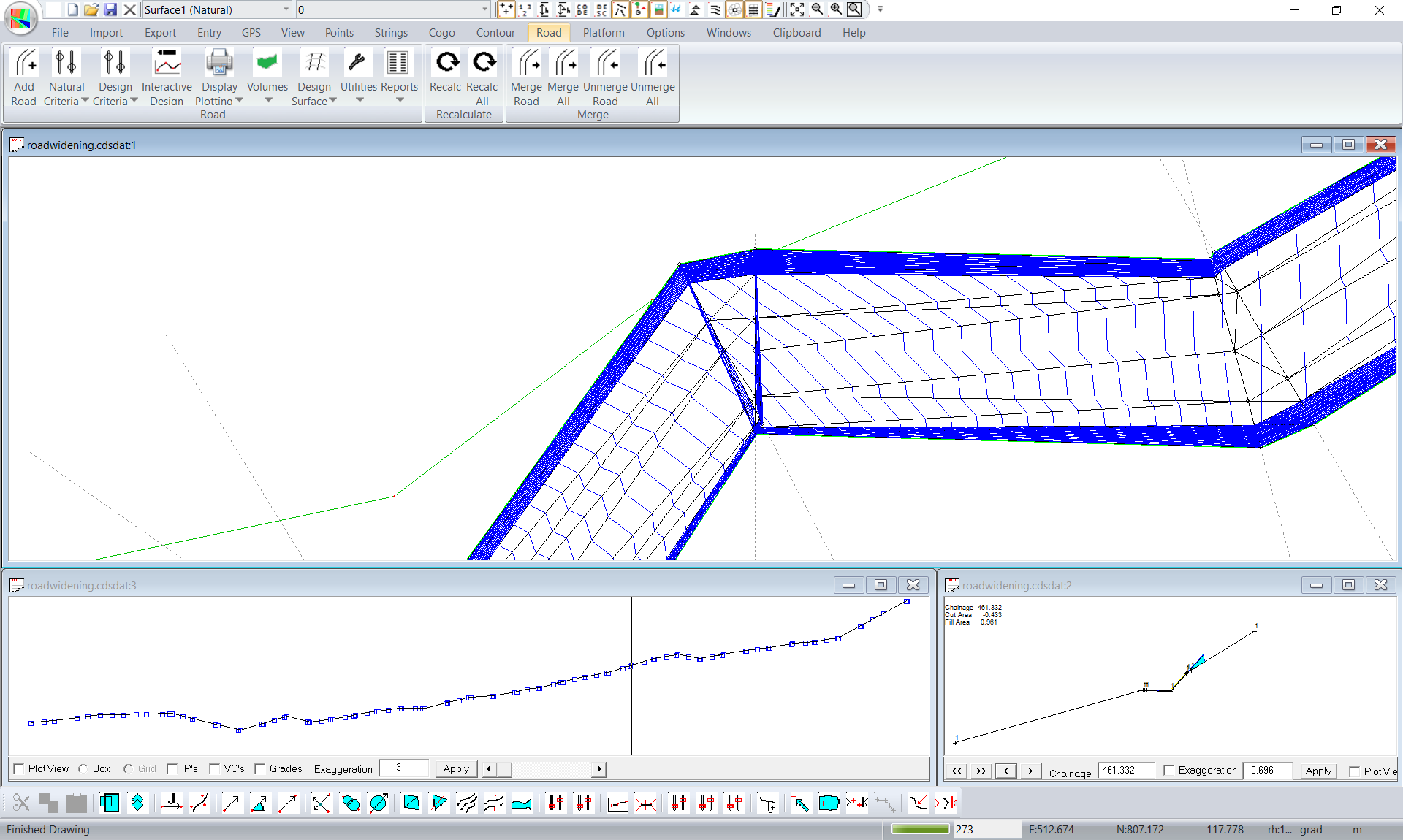
In this case the easiest solution is to delete one of the sections. I would choose the one on the straight. Display this in the section view. You drag your mouse around the profile view until you see the cursor in the correct position in the plan view. Left click in the plan view on the plan section and the appropriate section should be seen in the section view. Move the mouse in the section view and check plan view to confirm.
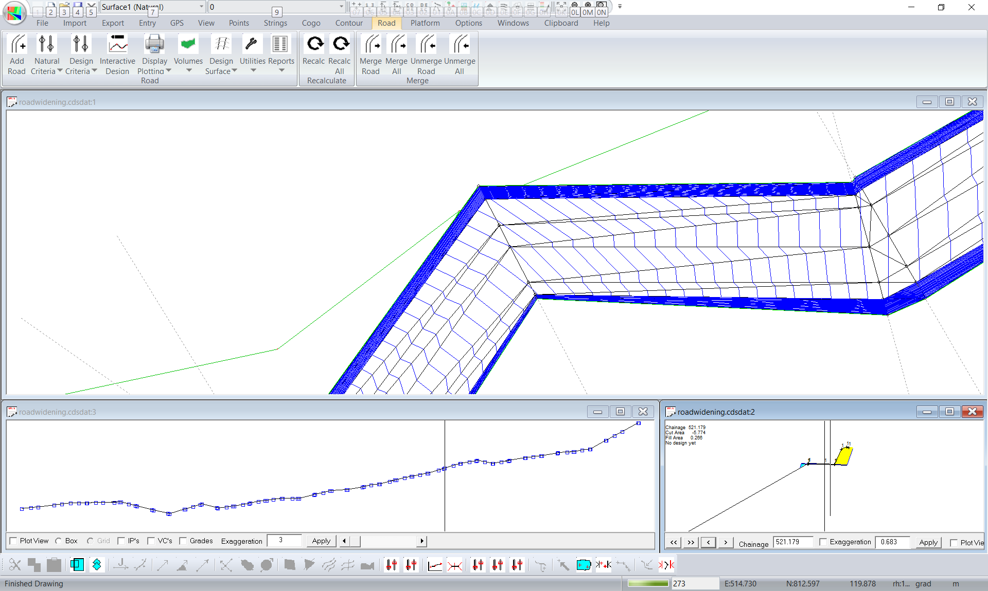
Right click in the section view and click on the delete section. Click Road -> Recalc to see the effect:
You can create a new DTM from the Road -> Merge menu item.
|