| < Previous page | Next page > |
|
Intersection Design Example
The following tutorial shows the steps and procedures that you could use to design and create an intersection. The tutorial uses the main road we have designed in a previous tutorial. We have designed a secondary road that runs off this road at an angle. Our design brief is to design an appropriate intersection between the two.
If you point your web browser to ftp.foresoft.com you can upload the file "intersection.cab". From the options menu (with no job open) you can restore the job to your data directory. If you open up the job you will observe the main road as designed previously as well as the secondary road. The secondary road has been designed through the main road. There is less work to do if it starts outside the main road as there is less cutting of string lines etc.
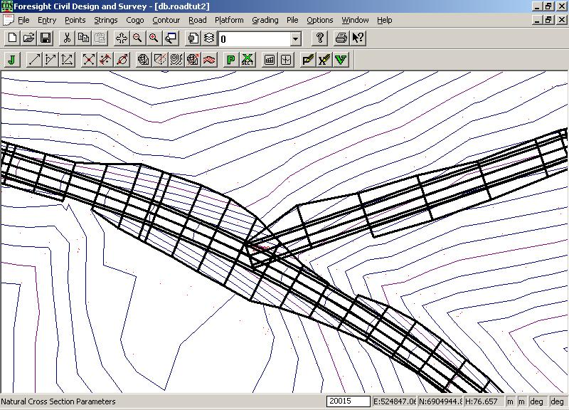
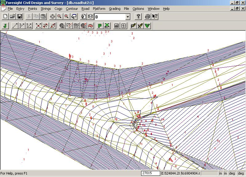
If you open up the intersection job you will see the following as seen below:
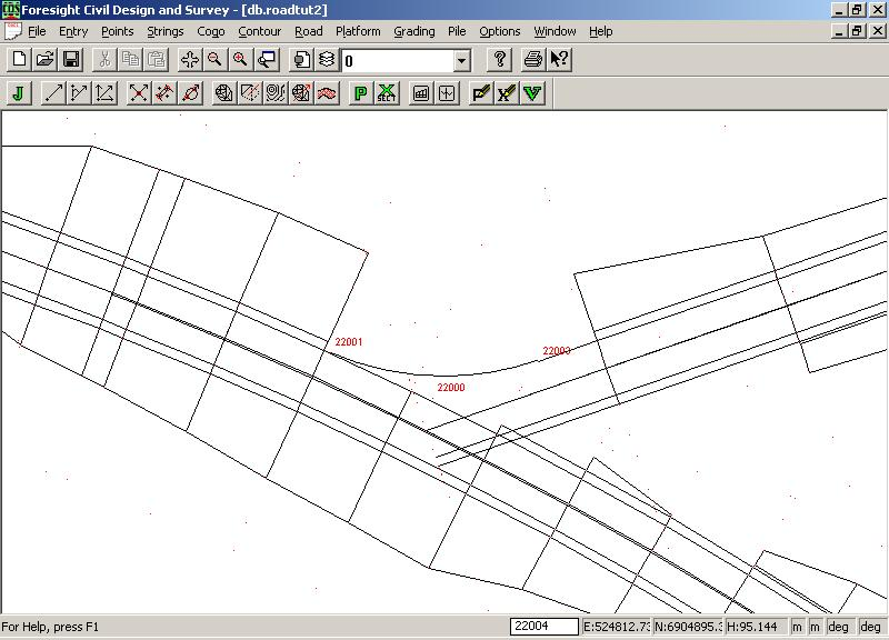
The first step is to cut the lines and delete any points that run along the left edge of the main road. We don't want the pavement of the main road to be affected so we don't cut the ledge string running along the pavement. Cutting a line in CDS is a two step process. First step is to split the appropriate string. To do this select the offending string and run the "split" option under the string menu. Select the point on string we wish to split at. Two strings are created from the initial string. Then from the string menu select change and remove the first couple of points from the second string created. Repeat for the other edge string. We also need to remove some of the initial points from the strings making up the secondary road. Again you can use the string - change option or alternatively under strings - utilities there is a drop points from strings menu item that you can use. After running the above we can get what we have below.
The next step is to create the kerb return that joins together the left edge of pavement. To achieve this we need to return to the Cogo routines. The first step is to calculate the intersection point of the left pavement edges. Use the Cogo - Intersect Bearing & Distance - 2 Bearing Intersect routine. Remember you can click in the start points from the screen for each bearing. Also when putting in the bearing in and bearing out use the "P" command. With the mouse click into the bearing in box. Then type P. Click on the first point of the line that defines the bearing and then the end point. The bearing is calculated for you and the bearing displayed. Repeat for the bearing out. Hit the apply button and number the point 22000. Next step is to calculate an arc that joins these two left edge strings smoothly together.
From the Cogo menu select "Curves" an then "IP & Radius". The 22000 point we have calculated previously is our IP point. Fill in the "bearing in" and "bearing out" items. Remember to use the "P" command and click in the appropriate points from the screen that define the in and out bearings. In this example we have used a radius of 30 meters. The value to use being up to your professional experience and judgement.
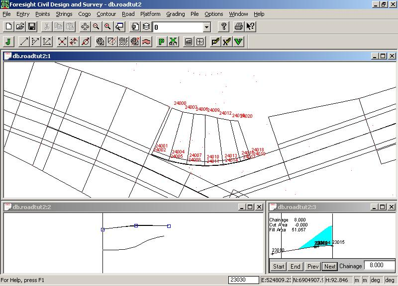
Next we use our road routines to create a small road that follows this arc around. In Australia this arc we have designed is called a kerb return. The steps that we run are as follows
The result is seen below.
We can now create a design surface to check our design. You may need to delete any points from road 2 that are lying on the surface of road1. Also any design points from road1 that are lying in the transition area need to be deleted as well.
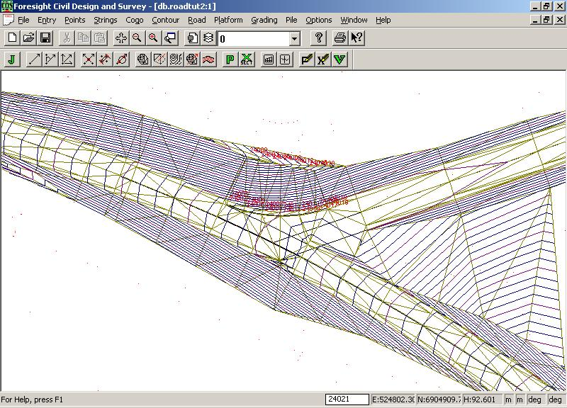
The next stage is to create the kerb return for the right hand side of the road. This is an identical procedure to that already done for the left hand side. The finished design is seen below with the design contour shown so that you may check for drainage and smoothness etc. If you are not happy with the design you can go back and delete the appropriate design points and redesign the appropriate profiles and recreate the design points. You may also need to define appropriate break lines in your design to create the appropriate contours.
 |